

|
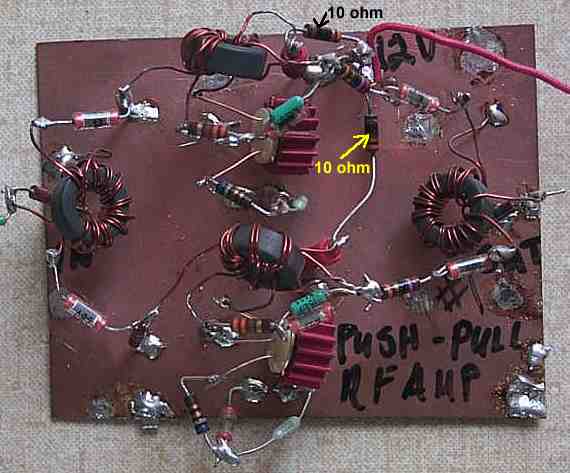
Shown above is the bottom one half of the dual 2N5109 amplifier. The one turn loop is wound through the FT50-43 core of the 2N5109 transformer. One turn is just one time through the center of the core, as shown in the image. The "To +12" lead goes to a 10 ohm resistor, and then connects to a +12 power supply, as shown in the schematic below. The 10 ohm resistors feeding each of the amps is shown in the image below. |
|
This schematic is slightly different than the one on the previous page. It is wound as a bifilar, but the turns are not connected to make a bifilar winding. One turn is connected to the input and ground. The other turn is connected to the inputs of the amplifier. After taking the amplifier out of my receiver, I discovered that this was the way I had wound the cores. This may be simpler to set up than the trifilar shown in the previous page. This is probably not the way Rohde intended, but it works. Gain is about 12 to 14 dB. If you are having problems getting the circuit to work, set up the transformers (T3 & T4) as shown here first, then experiment with a trifilar winding as shown in the previous page. The second amplifier is built identical to this one, see image below. |
|
Note the input and output transformers, they are wound with two windings, one connected to the input and ground, and the other to the inputs of the 2N5109s. The circuit above worked great for me, but winding a trifilar to get a true 1:4 impedance transformation at the input and output (4:1) would probably give better matching. The transformers as I have built them would be much easier to set up, and I would suggest this configuration when first building the circuit. The trifilar winding can drive you crazy. |
Send E-Mail || Amateur Radio Receivers || Super Receiver Circuit Details || RF Amplifier || The 2N5109 Amplifiers