

|
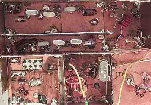
The image shows the complete crystal filter assembly. All the PCB pieces are 2" by 2", approximately, which is obvious. When I built this I never dreamed I would be taking a picture of this fine work and putting it on the internet. But it works! The signal arrives at the crystal filter (at the bottom right), to the 2N5109 amplifier, then into the homebrew diode mixer. The crystal oscillator is to the left of the mixer. The 455 KHz output comes out the bottom of the mixer to the 455 KHz matching circuit. The relay at the bottom left switches the assembly in and out of the receiver circuit as needed. |
|
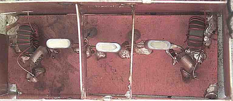
A close-up of the crystal filter. The cores are FT50-43, caps are 300pf poly, and the crystals are 3.547 MHz. Shields and plenty of spacing is used to maximize the effectiveness of the filter. The bottom PCB is 6" by 2". |
|
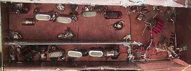
The signal enters at the top left, through the first filter, amplified by the 2N5109 amplifier, through the second filter, and out down to the SBL-1 DBM mixer. The crystal oscillator is to the right of the mixer. The output matching circuit is below the SBL-1 DBM mixer. The circuit to the right of the crystal oscillator is part of the VFO and is not part of the filter circuit. |
|
A close-up of the filters. They aren't built exactly the same, but close enough to work. The 2N5109 amplifier overcomes any mismatches and helps blow the signal through the second filter to the mixer. |

|
The 455kHz ceramic filter is different than the one above, a Murata CFU455H. It is located in the middle bottom of the mixer/matching square, a black square object. The SFU455A is rated at 10kHz bandwidth at 3dB, whereas the CFU455H is rated at 3kHz bandwidth at 6dB. I have found the type of filter is not important. The filters main job is to lower the noise level out of the mixer and clean up the harmonics. The filter could be left out with very little difference in performance if one can't be found or a tight budget |
Send E-Mail || Amateur Radio Receivers || Super Receiver || Super Receiver Circuit Details