

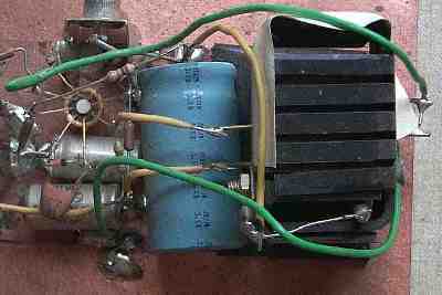
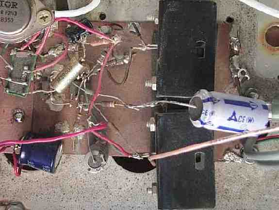
| Above is an image of the "dead bug" version of the schematic at the top of the Audio Amplifier page. The heat sinks on the right are two TO-3 heat sinks with the transistors inside and facing one another. The "E" and "B" pins are shown on the outside of the heat sinks. |
|
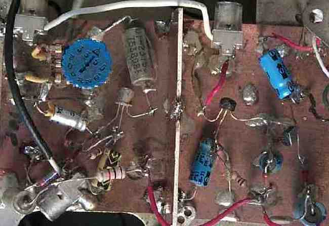
Close up images of the discrete audio amplifier from the 160 Meter Receiver in the Solid State Design book from ARRL. The LM301 IC is shown mounted upside down wired "dead bug" style. |
|
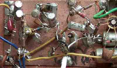
The input is at the bottom left at the phone connector. The cable comes from the product detector. The output of the pre-amps is at the top of the capacitor (negative side) at the top right of the image. The picture shows two pre-audio amplifiers. A PC mount volume control was added to the first amplifier to adjust the output of the first pre-amp to match the various IF/product detector circuits that I have been using over the years. The second amplifier is a two transistor direct-coupled audio amplifier. The direct-coupled amplifier comes from the Progressive Communications Receiver. In the Progressive Communications Receiver, the audio is muted by grounding the emitter of Q2, which would be simpler than wiring in a the relay. The white wire (at the two phono connectors at the top of the image) connects the output of the first pre-amp to the input of the second pre-amp. |
|
The heat sinks for the output transistors are insulated from the PCB board by electrical tape. The two output transistors can be mounted on a common heat sink, as the collectors of the transistors are tied together, but the heat sinks must be insulated from ground. The IRF243 switches the relay. The gate voltage of the IRF243 is controlled by an SPST switch on the front panel of the receiver. This provides a mute switch for the receiver. The IRF243 MOSFET is way over rated for the application (over 250 volts), but is reliable and was handy. The MOSFET is not needed, as the relay could be controlled by the switch without the transistor. The LM301 is shown "dead bugged" mounted upside down right below the IRF243. This part may be difficult to get, but may be purchased from BG Micro in Garland, Tx. The large output electrolytic capacitor on the center right connects to a phono connector that goes to another phono connector on the back of the receiver for connecting to a speaker. |
|
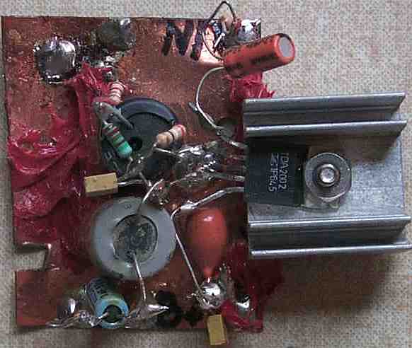
The TDA 2002/LM383 audio amplifier "dead bugged". This is a very easy ""dead bug" project and has worked very well. It can be wired into new prototype receivers very easily. The pre-amplifier is not shown. It was never done dead bug style. The circuit is the one in the Electroluminescent receiver and the complete circuit was laid out on a PCB and never went through the "dead bug" stage. Some feedback from a customer indicated that a low-noise op-amp has better performance as a pre-amp rather than the transistor design proposed in the schematic. |
Send E-Mail || Amateur Radio Receivers || Super Receiver || Super Receiver Circuit Details