WinWarbler Online Help Contents
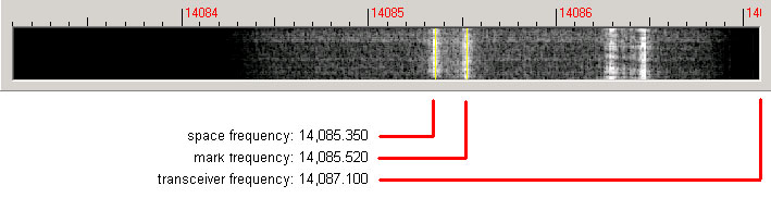
A RTTY signal involves two frequencies, referred to as mark and space; the sequence of 1s and 0s representing a character are conveyed by appropriately switching an RF carrier between these two frequencies. The switching occurs rapidly enough that, when seen on a PC-generated audio spectrum display, a RTTY signal appears as two peaks and on a waterfall display as two lines. By definition, mark is the lower of these two frequencies, and space is the higher of the two; most amateur RTTY uses a shift - the frequency difference between the mark and space frequencies -- of 170 Hz. By convention, most amateur RTTY is transmitted on lower sideband (LSB). Thus when viewing a RTTY signal on a spectrum or waterfall display whose frequency increases from right to left, the left-most peak or line represents the signal's space frequency, and the right-most frequency or line represents its mark frequency. To avoid confusion, RTTY operators refer to a station's mark frequency when making schedules or reporting QSOs. So when P51DX is spotted on 14,085.52, it means that his mark frequency is 14,085.52 kHz and his space frequency is 14085.35 ( assuming a standard 170 Hz shift):
The tuning display at the bottom of WinWarbler's main window provides a visual indication of RTTY activity across a 2.9 kHz frequency range; the top of this range is set by the contents of the xcvr freq selector (in kHz), located in the QSO information panel. Note that your transceiver's bandwidth and filter settings may attenuate signals in parts of this range. You can select a waterfall or spectrum display, using settings in the Tuning Display sub-panel. A waterfall display can be presented in monochrome, or synthetic color using a color lookup table devised by AE4JY; a gain setting allows you to further control this form of tuning display. The spectrum display's trace color is set by the trace color setting; its background color is fixed at black.
If sub-band highlighting is enabled, the frequency scale above the tuning display is rendered in green for frequencies within RTTY sub-bands, and in red for frequencies outside of RTTY sub-bands; you can customize the definition of these sub-bands.
The tuning display shows the mark and space frequencies as yellow traces. You can change the colors of these traces via WinWarbler's display settings. You can control the width of these traces via the frequency trace width setting. If the transmit panel's net control is not checked, WinWarbler's transmit mark and space frequencies will appear in the tuning display as a red traces. Decoding and transmission are only possible if the mark and space tones are greater than 100 Hz, and less than 3000 Hz; if you select mark and space frequencies outside this range, the traces will be shown as dotted rather than solid lines.
To change soundcard RTTY frequency, click in the tuning display to choose a new mark frequency; the frequency you select will appear in the receive panel. If there's a nearby signal and the Automatic Frequency Control box (AFC) is checked, WinWarbler will adjust its frequency to track that signal. If you are simultaneously receiving RTTY via both soundcard and external modem, you must first select the soundcard RTTY receive pane before clicking on a new mark frequency. Do so by clicking the mouse anywhere within the soundcard RTTY receive pane -- its channel label will turn red to indicate this selection.
Clicking the Default button in the Main window's RTTY Receive panel sets the mark and space frequencies to default values determined by the AFSK Optimal Offset or FSK Optimal Offset and the Shift settings:
| Modulation | Mark Frequency | Space Frequency |
| AFSK | carrier + AFSK Optimal Offset + ( Shift/2) | carrier + AFSK Optimal Offset - ( Shift/2) |
| FSK | carrier + FSK Optimal Offset + ( Shift/2) | carrier + FSK Optimal Offset - ( Shift/2) |
The signal quality indicator in the Receive panel displays the quality of the signal being received by the selected channel. You can adjust the squelch threshold setting by clicking within the signal quality indicator.
The receive panel's XY display plots the mark and space frequencies as ovals; when these two ovals are at right angles, the signal is properly tuned. if you find the waterfall or spectrum scope sufficient for tuning, you can disable the XY display and reduce the load on your PC.
To optimize reception, you can enable MMTTY's bandpass filter by checking the BPF check box. The shape of this filter can be controlled via the MMTTY Setup dialog.
If the station you're monitoring is transmitting reversed tones, check the Receive panel's reverse box; to transmit reversed tones. Modifying this checkbox automatically updates the receive setting in the Reverse panel on the Config window's RTTY tab.
Using the MMTTY Setup dialog, you can configure the MMTTY engine to use one of three discriminators: an Infinite Impulse Response (IIR) resonator, a Finite Impulse Response (FIR) filter, or a Phase-locked Loop (PLL). You can can adjust the IIR resonator's bandwidth, or specify the number of taps in the FIR filter. Besides discriminator settings, you can also configure the limiter and the low-pass filter. Providing all of these settings makes MMTTY exceptionally flexible; however, tweaking this many settings while trying to work BQ9P through the auroral flutter is clearly impractical. To address this problem, MMTTY provides profiles. A profile is a named array of values for each of MMTTY's decoding settings. When you select a profile, all of MMTTY's decoding settings are simultaneously established. MMTTY lets you define up to 8 profiles; profile definitions are stored in a file named USERPARA.INI that resides in your WinWarbler folder. The USERPARA.INI provided in WinWarbler's Profiles folder contains 5 predefined profiles:
standard RTTY
fluttered signals
fluttered signals (FIR)
multi-path
23hz RTTY
To gain access to the above profiles, copy USERPARA.INI from the WinWarbler/Profile sub-folder to the WinWarbler folder before starting WinWarbler. WinWarbler lets you choose from among the profiles in your USERPARA.INI file via the Profile Selector in the Main window's RTTY Receive panel. Selecting a profile can change MMTTY's Unshift On Space, Reverse, and Keyboard Mode settings; you may need to modify these settings if they don't match your setup and/or preferences.
You can use MMTTY to customize the above profiles, or create new ones that you can access via WinWarbler. If you've developed your own profiles using MMTTY, copy the USERPARA.INI file from your MMTTY folder to your WinWarbler folder. You can also directly edit your USERPARA.INI file with a text editor like Notepad, but the codes found in this file are terse and undocumented.
Information decoded from the receive frequency is sequentially appended to the soundcard RTTY display pane. The display pane has a vertical scrollbar along its right side, allowing you to view information which has scrolled off the pane. The only limit to each display pane's information retention is the amount of free space on the disk drive hosting WinWarbler. You can change the font name, style, size, and color used to display this information via WinWarbler's display settings.
If you are simultaneously receiving RTTY via both soundcard and external modem, their receive receive panes are separated by a "splitter" bar; by dragging this bar with the left mouse button, you can reallocate available screen space between the two panes. Clicking the right mouse button over a receive pane produces a pop-up menu that includes an Equalize all receive panes entry; selecting this entry equally divides the available space between the soundcard RTTY receive pane and the external modem receive pane.
Because RTTY uses the LTRS character to switch from sending characters in the figures set to characters in the letters set, and the FIGS character to switch from sending characters in the letters set to characters in the figures set, a garbled LTRS or FIGS character can result in the misinterpretation of the subsequent word. To compensate for this, clicking on a received word while depressing the Ctrl key will replace the each character in that word with its analog in the opposite set, and toggle the character's underlining in the Receive Pane. If you receive a garbled word, try Ctrl-clicking it; if that doesn't make it intelligible, Ctrl-click it again to return it to its original state.
The figures character Bel (the analog of S in the letters set) is rendered as ~.
For this purpose, a word is considered to be a sequence of characters delimited by a space or newline character; each Receive pane acts as if it begins and ends with a newline character.
To freely scroll a receive pane, you must first suspend the pane's display of incoming information; do so by clicking on the color-coded panel to the left of the pane you wish to scroll. A pane's channel label blinks while it is suspended. To resume the display of incoming information -- including that which arrived while the display was suspended, click on the color-coded panel to the left of the pane. You can suspend a pane for up to an hour without loss of incoming information.
To copy text from a receive pane to the Windows clipboard, use the standard Windows left-click and drag gesture. This gesture automatically suspends the pane. Click on the color-coded panel to the left of the pane to resume the pane's display of incoming information.
To facilitate logging, double-clicking on a word in a receive pane copies that word to the appropriate QSO Info panel item.
The contents of the QSO Info panel items are maintained separately for each receive channel; whenever you switch channels, these items are updated to reflect whatever information you have captured from that channel. This makes it easy to incrementally capture information as you monitor several QSOs.
Clicking the right mouse button over a receive pane produces a pop-up menu with four commands:
WinWarbler automatically interoperates with Commander, an transceiver control program for Icom, TenTec, Kenwood, and Yaesu radios. If WinWarbler and Commander are running simultaneously, WinWarbler's xcvr freq selector will automatically track your transceiver's frequency as you QSY; it does not matter in what order the two programs are started. If you modify the contents of the xcvr freq selector and then strike the Enter key, or if you select a new frequency, WinWarbler will direct Commander to QSY your transceiver to the specified frequency
Optimizing the Audio Offset Frequency
The frequency shown in the Receive panel is the sum of two components: your transceiver frequency, and an audio offset frequency in the range of 0 to 4000 Hz. Your transceiver's filters may make it difficult to receive and/or transmit signals that fall near the lower or upper ends of its audio passband. Furthermore, transmitting with a low audio offset -- say 1 kHz -- can generate harmonics that fall within your transmitter's passband and therefore produce QRM up the band. If Commander is running, clicking the Opt button directs it to change your transceiver's frequency so that the center audio offset (the midpoint between the Mark and Space audio offsets) is a value you specify for AFSK operation or a value you specify for FSK operation. Since the transceiver frequency and audio offset frequency are simultaneously adjusted, you can use this function during reception and lose no more than a character or two. You can also activate this function by right-clicking in the the waterfall or spectrum display while depressing the CTRL key; if the waterfall right-click box is checked, you can activate this function by right-clicking in the waterfall or spectrum display without depressing the CTRL key.
The opt button is disabled if Commander is not running; it is also disabled during transmission.