This project was the result of living on the road as a National Trainer for a large optical company. I missed being able to keep up with the ham activities, and I wanted an inexpensive yet sensitive receiver which could operate under hotel room conditions. That being: my only antenna just might be a clip lead to a window screen. I remembered that my two stage regenerative rigs would be especially sensitive with small antennas. But at frequencies much higher than 40 meters, they were cranky things to tote around, and required a stable operating environment. Once bolted down and grounded and adjusted, the two-tube marvels were great. But for 20 meters, I wanted something that I could throw on a bed-side table, plug in and GO! And, I wanted it to be as simple as the regens, using my favorite venue: tubes. This radio must glow in the dark!!
The circuit in fig. 1 (.bmp) can best be described as an RF converter followed by a tunable regenerative detector. There are many advantages to this scheme:
This type of receiver represents a period of technological crossroads, a time when old schemes and philosophies were giving way to new ones. TRF type receivers were grudgingly being given up for the more sophisticated superhets, both in the amateur and in the Broadcast industry. It was a financially difficult time as well, and many of these more advanced designs were just out of reach for the average ham of 1936. A three dollar tube could equal a week's food allowance. If you had work. Otherwise it might have meant the bread line. This environment spawned many design innovations, some of which were strokes of genius. Some were quaint. All were meant to make a dollar go as far as it could. One way of upgrading the old TRF without blowing the budget was to just make the converter stage and follow it with the TRF, using it as a variable IF tuner. Mr. Frank Jones came out with an "every man's" type handbook which enabled many hams to build versions of more expensive commercial devices on a Depression budget. One such innovation was the "Super-Gainer" receiver.
This was a true superhet design incorporating a tunable first detector, generating a fixed output at a very low frequency, about 100 KHZ or so, followed by a regenerative detector. This design put to practical use the best of both circuits. It is very hard to beat a regen detector for sensitivity and selectivity at those frequencies! Since the Local Oscillator provided the tuning, only a few hundred KHZ from the receive frequency, much care had to be taken in it's construction, for stability's sake. The potential existed for the variable Local Oscillator to react to the dynamics of the receiver input. This is one reason why many hams kept the Local Oscillator as a separate circuit from the actual Mixing circuit long after pentagrid converters were available .
As economic times got better, hams were better able to get into the technological strides of the day, with it's buffered RF stages, multi-element converter tubes, AGC, Single Signal Crystal Filtering, "Silent Cans", and all the niceties that eventually eclipsed the old regenerative receivers and regenerative-superhets, at least on the HF bands. High Schoolers were buying Sky Buddies by 1939.
Let me add an observation here. Regenerative receivers were not replaced because of faulty, erratic behavior, such as I read in today's descriptions of them, or else they would not have lived far beyond the early 1920s. In fact, many radio manufacturers continued to use the principle of regeneration in their products up onto the 1960s, and even beyond (after all, what was your basic Q-multiplier, anyway?). The descendence of the Regenerative Receiver occurred with it's inability to accommodate the technology then developing. They were viewed as sort of a technical cul-de-sac. All attention was therefore diverted to the superhet. And why not? They are better performers, albeit more complex devices, and the niceties are. . . well, nice to have. But the regenerative detector remained, and is still to this day a viable scheme, when properly constructed and utilized. The type circuit described here is a version of the Frank Jones Super-Gainer. The chief difference lies in the tunable detector approach. This design places the tuner in a more stable low frequency stage, and utilizes a more stable crystal local oscillator for the mixing circuit. In my opinion, this makes for an all around more rugged design, and simplifies things considerably. In that the detector is regenerative and acting as the primary selectivity and tuning device, I opted for the term "Regenerodyne" for this approach.
"Regenero" - for having been brought forth from regeneration, and
"Dyne" - for "powered". (Regeneration being the primary dynamic, or "power" that makes
this scheme worthwhile.)
Regenerodynes, therefore, differ from Mr. Jones' Super Gainer in that the LO is fixed, and the detector, which is always regenerative, is a tunable detector.
While I have no actual examples of this exact receiver ever having been built, it was certainly
possible to do so, as the price of crystals had dropped considerably by the end of the Depression,
and the crystal controlled transmitter craze was well under way. In the late thirties, around
1936, there was a lot of ten metre activity, and lots of hams were having great results coupling
their TRF low band rigs to ten metre converters. This is the closest thing to a Regenerodyne I
have actually found. And that's all it is, really. A TRF following a converter.
Return to top
In my version, I chose to depart from austere 1930's accuracy in the name of practicality. I use parts from the 1940s and 1950s. Especially the crystals. I use the HC-6 type, because the larger FT243 type proved to be very slow starters. I also use a silicone rectifier in the power supply, which is built separately and is kept out of sight, anyway. Speaking of the LO, almost any type of mixer could be used. I chose mine because I had the pentode (6J7) and the triode (6C5) handy. You may have your favorite you like to use. For other ideas, look at the older handbooks. Take care if you choose to use a pentagrid mixer. I have seen it pull the LO under certain conditions (although it is tempting to use them. This would remove the need of the LO tube, but one of the design goals was stability, and in simple circuits, this could prove a liability.) In my very conventional scheme, the LO signal is injected at the cathode of the 6J7 through a .01 uF ceramic disc capacitor.
Almost any arrangement of this circuit can be employed, as well as any layout. I used an aluminum chassis for mine because I like the look of late thirties Homebrew. The tubes I used were local military surplus specials, but many substitutes can be used. I would suggest that you keep the filament wiring close to the chassis (underside) and RF leads elevated from the chassis. Especially the grid leak.
Keep in mind that the coils are affected by heat from the tubes, so keep them as clear from the tubes as possible. If you are using an outboard power supply, ground the chassis of the receiver to the chassis of the power supply: do not depend on the (-) negative lead to provide common ground for RF.
Although this receiver can be built on anything from wood to steel, I recommend the use of a metal cabinet when possible. Or at least a good, solid metal front panel.
Three coils are involved in this transformer, L3, L4, and L5. The coil form I recommend is the
1-1/4 inch plastic 35mm film canisters. Wind L4, the detector grid coil first. Next, wind L5
1/2 inch above L4, winding in the same direction as L4. At this point you are ready to wind L3.
I used double-sided tape to wrap around L4, and then wound L3 directly over L4. L3 matches the
turns of L4. This provides a rough matching system. Notice that the mixer output coil L3 is
untuned. This is to minimize the load on the detector and to allow for a broad IF "window" as
opposed to a fixed single frequency. Hence our IF transformer is tuned entirely by the detector.
If you follow the turns indicated on the schematic, you should have your detector tuning pretty
much in the 2.8 - 3.3 MHZ range.
Return to top
The incoming signal is coupled to the mixer through L1 and is tuned through L2/C1. The local oscillator signal is introduced to the front end by applying it to the cathode of the 6J7 (or 6K7) through a .01 uF capacitor. I may point out again that this is only one way of several to inject the local signal to the mixer; look at the old handbooks from the 1950s and 1960s for more ideas. It is important that there isn't too much injection. In this condition the local signal may overload the pentode, pass through to and block the detector. An overloaded mixer can also interfere with your antenna preselector tuning.
The triode used in the local oscillator was one I had handy from an old National SW-3 project. Use what you have handy, using the proper voltages, biasing and such. No tight tolerances here, gang!
The unusual aspect of this design is the untuned nature of the IF transformer. If the mixer output was tuned, it would load down the detector to the degree beyond that which I would call stable, unless L3 and L4 were very decoupled. I suppose a dual-ganged variable capacitor could work tuning both L3 and L4, but another thing would be sacrificed, which is simplicity. In my hands the untuned primary approach works. This idea for RF transfer is nothing new. I got the idea from a QST article describing the Bearcat Model 3-B three tube regenerative (August, 1929). In this old classic, the untuned RF amp is coupled to a multi-detector in the same manner, for the same reasons. In more modern solid state designs, converters with untuned or wide band outputs were frequently followed by eighty meter regen or DC receivers for multi-band operation.
Images are kept to a minimum by a combination of the high Q inherent to the regenerative circuit, and an IF that is low, but yet not too low thus keeping the image tolerably far away ( 6 MHz for a 3 MHz IF). This is why I chose and IF "window" of about 3 MHz. At this frequency the detector performs very well, exhibiting good stability and selectivity, providing decent bandspread to boot. Coils are no problem to wind for these frequencies, either.
Of course the detector is nothing more than the classic 'gennie itself. Therefore there is really not a need for a BFO. Which would be hard in this set-up because it, too, would have to track along with everything else. Also, no high gain audio stages are needed, as with Direct Conversion receivers. The tube chosen for the detector is a dual triode of late thirties and early forties vintage (6SN7). Another tube that works, which has an older pedigree but is still reachable is the 6F8G, used in the mid 1930s for simple receivers. The more modern 12AU7s, 12AT7s and 12AX7s would work as well.
Since I have more low impedance head-sets than the classic Baldies around the shack (perish the thought!), I borrowed an audio output transformer to give me an eight ohm output. Then I took the opportunity to place a .22 uF capacitor across the primary. This removes the sonics ( hi audio frequencies) from the AF output for more comfortable listening. If you wish to use your venerable Baldies, Frosts or Federals, just hook them across the B+ from pin 2 of the 6SN7, but be wary of the B+ present at the terminals on the ear pieces. You may want to use an isolation capacitor, around .001pF.
A word about the RFC at the detector output: i have used everything from a 2.5 mH to a 25 Hy choke here. Use as large a reactance you can, even the plate side of a plate-to-voice-coil transformer works nicely. For that matter, it functions as a filter choke in a low current plate supply as well. Good way to recycle old speaker transformers.
The whole receiver is powered by a 90 - 100 volt DC source, which can be obtained by connecting
two six volt filament transformers secondary to secondary, or perhaps you have a low current
transformer in your junque box good for 100 volts or so. I use a solid state rectifier in half
wave pi output format, (using the primary of that old audio transformer as the filter choke).
As you can see, there is a lot of room for creativity here. Such is the spirit of these older
designs.
Return to top
Remember as you lay out your chassis or breadboard to follow the same construction precautions
as for building a VFO. Keep frequency determining components away from heat generated by the
tubes, such as the coils and capacitors in the tuned circuits. Shield all controls, like the
tuning dials with a grounded front panel, such as an aluminum panel, copper clad PC board, etc.
Keep the filament wiring well away from grid circuits and close the chassis to avoid hum pickup.
Rugged construction, stiff wiring, and good shielding is essential in ANY receiver or transmitter
design.
Return to top
Once you have given it a thorough wiring check, hook up the B+, filament and ground connections and turn it on. ( I always find myself looking for smoke at this point, so if there is none, proceed.) If you have wired the detector correctly, advancing the regeneration control should cause you to here the point of regeneration, a rushing sound which increases as you advance the control. The point at which the sound just begins is the 'threshold', the point of maximum sensitivity and minimum stability. Your control should allow the detector to glide smoothly into the regenerative state, not just 'plop' into it like some of the latter-day blooper articles describe. If it does plop, or just pop into regeneration, there is too much coupling between L5 and L4. Either reduce the windings or increase the space between them to reduce coupling. If you do not hear regeneration occurring at all, check to make sure L4 and L5 are wound in the same direction. As well should L3. It takes only about 20 - 35 volts DC to bring most regeneratives to oscillation. The 25k ohm pot used as the regeneration control should be sufficient to reduce the B+ to the detector sufficiently.
Next, connect an antenna wire about 10 or 20 feet long, and plug in the LO crystal. With the detector oscillating, tune the antenna preselect until you hear a rise in signal or background noise volume. You will find there are two spots on the preselect range where this happens, one on either side of the LO frequency. You may also find a spot between them that blocks the grid, a dead spot. This is the preselect tuning the LO frequency. This dead spot should not be very wide, however the LO signal can be strong enough to cause the detector to cease to oscillate. The nice thing about higher frequency IF s is that your actual listening frequency is far enough away from the LO frequency that it should not interfere. If it does, reduce the voltage to the LO. I have never had this problem, the voltages described here should preclude this from being a problem Increasing the capacitance (C2) through which the LO injects the pentode may help this situation , should it occur. Some loading is to be expected, though, if the preselect is actually tuned to the LO frequency ( which is one way to determine of the LO is even working.)
If nothing happens when you plug in your crystal, double check to make sure the LO is oscillating. IF you tune in a signal, pull out the crystal. If the oscillator is working, the signal should disappear, and other signals may be heard because you are now listening to the IF without the mixing product.. If you hear no change, the LO may not be oscillating. Check over the wiring: there is not a lot to go wrong. Just a reminder, those large older transmit type crystals like the FT-243 type can be very slow starters in this oscillator. That's why I recommend the newer HC-6 type instead.
Operation of this receiver is similar to that of a regenerative receiver. You have a regeneration control, a tuning dial, perhaps a bandspread, and an antenna preselect. The antenna preselect can be used as an RF gain control, an antenna trimmer of sorts, and a band selecting device. The first thing you want to do once the receiver is up and running is calibrate the dials. You will want to mark the bands on the preselect and the frequencies on the tuning dial(s). If you followed the coil descriptions closely, your detector should be tuning around 2.8 to 3.3 MHz, or thereabouts, so if you use a 10 MHz local oscillator crystal (LO xtal) you should have no problem finding the 40 meter band.
( 10 MHz (LO) - 3 MHz (IF) = 7 MHz )
You may have to pad your tuning capacitor to get exactly where you want, but once you have found your bearings, you can use other crystals for other bands and know right where you are at. I use a 10.0 MHz crystal for 7.0 MHz, a 13.0 MHz crystal for 10.0 MHz ( actually, 30 meters is 10.1 MHz) and a 17.0 crystal for 14.0 MHz. Note again that for every crystal there exists the image frequency, which has the potential for giving you two bands for one crystal! This is reminiscent of the Drake 2 series receivers where you could use the antenna preselect to get an extra "bonus" band. One thing that can also be included in the LO, which I myself have not done, but which is certainly possible, is to place a trimmer cap in series or parallel with the LO xtal to vary it some, for fine calibration.
Once this rig is working and you get used to the nuances of it's design, you may find it to be
extremely versatile and easy to platform from.
Return to top
Some added construction comments:
Except for the detector coil, everything is pretty standard and straight-forward. Looking at the old magazines and photographs, builders and manufacturers often kept the main tuning vernier in the center of the front panel. When they were offset, the remaining controls were usually grouped on the other side of the panel to balance out the look of the controls. Those builders of yesteryear wanted a good looking rig to grace their shacks!
Your panel controls should be: coarse, or main tuning, fine tuning, regeneration control, and front- end preselect. You may not want to manually change crystals each time you want to change bands, so you may want to add a band select switch do this instead. You may want a stand-by switch for use with your trusty QSL-40. This might be accomplished by switching out the B+ to the audio. You may harbor a secret desire to put a "magic eye" signal strength indicator on this receiver ( or on any receiver for that matter ) which might be done by sampling a bit of rectified audio voltage to the grid of a 6E5, and biasing it with a 1 or 2 megohm resistor.
This receiver can be built on wood, masonite or on a metal chassis, as mine are. If you choose the chassis mode, it might be wise to invest in some Greenlee Socket punches. They are expensive, but you will thank yourself over and over again through the years. I have had mine for over twenty-five years, only two sizes, one for octal sockets and one for SO-239 coax receptacles, which also happens to fit the nine-pin tube sockets. Tube socket holes can also be made with a drill, taper reamer, tin nibbler and rat-tail file. The front panel should be a solid metal piece, I used both aluminum and steel.
Tube arrangement is builder's choice. As mentioned earlier, be aware of coils and frequency determining components being placed too near heat generating components. If you use heat shields on your tubes, use the dark colored type. I usually use an out-board power supply to avoid hum pickup.
The front-end and detector coils were wound on plastic, but you can use any insulating form. If you use wood or card-board, make sure to seal it from moisture with Krylon acrylic spray. You may want to bake the wood first to drive out moisture before you seal it.
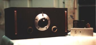
A word about the size of this receiver: it is really very small. Even using octal type tubes,
I have built my smallest table-top "eavesdropper" on an 8" by 5" chassis to mount in a SW-3 type
cabinet. This cabinet is actually smaller than the SW-3, probably 9" by 6" with a flip top. The
Vernier used is the old A type Velvet Vernier.
Return to top
I designed this receiver from information gleaned from years of reading those great old radio magazines and . These are a fantastic source of information. There are lots of secrets, helpful hints and insights that call from the forgotten past, and believe me, in electronics the past gets forgotten very quickly. How many of you remember Quad 8-tracks?
The pioneers of wireless have a lot to say to us today. Other good sources are the various Handbooks, published over the last eighty years, and, of course, the old gear itself. Also, as you visit the Hamfests and conventions, strike up a conversation with the old timers. They forgot more than most of us ever knew! I do not believe that any Amateur or SWL can fully appreciate what we have today, and where we are technologically without understanding where we were yesterday.
Many current Amateur Radio publications have featured some very good articles about old time gear from time to time. Keep your eyes open for these. Also, organizations such as the Antique Wireless Association have newsletters and periodicals containing all kinds of information. There is a magazine called Electric Radio which deals exclusively with tube gear, and as I update this article, I must note that the internet will provide many avenues of research. ( That may be how you are reading this piece.) There are discussion groups that use e-mail as their venue where information is posted by list members on a 'reflector' and is downloaded to all members of the list. Glowbugs and Boatanchors are two such groups that I am aware of. The background of the members of these groups is vast, some of them long time authors in the field, some engineers, some have been building rigs since the 1930s, and lots who are new at this, many are none hams. It is a great melting pot of ideas and enthusiasm, probably my first choice to seek information these days.
A major source of parts these days seem to be eBay and related organizations. These are on-line auction sites where you can find almost anything. Another more traditional source is the Hamfest. Flea markets may yield some goodies, though I find that in most of these places my best bet is to buy a non working piece of gear and use it for parts. I have had great success doing this with old Hi-Fi's and older military gear.
Military Surplus outlets might still yield useable items. Also, you never know what turns up on garage- sale tables. I have seen Drake Twins sell for next to nothing because the adult children of deceased parents had no idea of what they were. ( I told them, in all fairness.) The point is, good stuff is out there. Half the fun is finding them.
Vernier dials can be a challenge. Keep on the look out for these, even between projects grab
them when you can. The National Co. used to make a great dial and reduction gear system (PW)
which they employed in their famous HRO series receivers. These were available as aftermarket
items as well, and consisted of a geared dial with windows on the edges and a rotating toothed
disk behind the dial apron which turned at a slower rate than the dial itself. As each of these
windows reached the top of the turning arc, a digit would appear in the window. You could rotate
the dial fifty times and watch the numbers climb from 0 to 500 through the windows. Between each
window is ten hash marks. This dial was then coupled to the shaft of a 50 to 1 reduction gear,
built into a large grey housing which had one or two output shafts for the variable capacitors to
couple to. Not only do these devices allow for steady and stable rotation at a very slow rate,
they also isolate the tuning capacitor, and boy, talk about looking great on your front panel!!
These things make even a one tube TRF look like a bad boy. These are still surprisingly
available, many having been auctioned on the internet for less than ten dollars complete.
I purchased mine from a radio antique dealer for five dollars for the dial alone, and from
another dealer found the reduction gear for another five bucks! But if you cannot find what
you want, just use C7, the 35pF bandspread capacitor until you find that treasured Vernier.
With the 50:1 units, C7 can be eliminated. There are other good vernier devices out there, so
start hunting.
Return to top
Well, just some closing notes. I have used two 'regenerodyne' receivers in my shack for a few years now, and have been impressed by their reliability. One is built into a cabinet that reminds me of an HRO Jr., with the HRO dial. The other reminds me of an SW-3, only smaller. This is the one that amazes me the most because of the way I operate it. It is a night-stand piece, with a bolt-on 34 inch antenna. The power supply is kept under the night stand. I use it only for 20 meter CW reception and the low end of the 19 meter broadcast band (it will cover the lower 200 KHZ of each band). Many times I have heard a dx station call, and I would hear him fairly good on the whip antenna, only to find that after I got to the main rig in the shack to try and work him on the 24 foot vertical, his signal on the HW-101 was not much stronger. In fact, sometimes the QRN would be increased enough to actually get a better copy on the inside 34 inch whip! Go figure.
Of course, this radio is no Collins, and in all actuality, it operates just like a typical regenerative receiver. You have to advance or decrease the regeneration every 75 Kc or so. But I have a 20 meter regen that is as stable as an 80 or 160 meter regen. And I can pick up one corner of the cabinet about an inch and drop it, and it stays right there on frequency. I never worry about body / hand capacity effects. I can change bands without changing coils, and keep my dial settings. And since my original intention was to make a take-along type of receiver to use in hotel rooms, using a window screen antenna, I think it turned out all right.
Well, that's all, folks! Another old-time radio project-editorial. I hope you will enjoy, as I have, the fun of building, the taste of the past, the challenge of operating homebrew equipment, and the satisfaction of knowing YOU made it! Catch you on 40 cw some early morning.