Sometime after I received my Novice ticket in 1977, I came to the realization that there was no way I was going to be able to afford even a used rig, with swap-fest prices pegging the DX 40s and 60s at over thirty dollars! Let me tell you, working in the swampy fringes of Orlando Fla. in 1977, you didn't make a whole lot more than that a week! My wallet was particularly depleted because it was all that I could do to buy that Drake 2A receiver. Fortunately for us po-foak, the was on Gore Avenue in south Orlando, a place called "Skycraft", a military electronics surplus mecca for guys like us. 807's for fifty cents, BC-455s for five bucks, all the coax and connectors, tube sockets, vernier dials, man, everything was there!! And to make things even nicer, all these pre-war radio magazines were turning up free for the taking. So we wound up building 30's and 40's gear, not for nostalgia mind you, but because it was all we had, at least , as novices and budding generals. So, in the beginning, this transmitter, chassis and all, cost me around 5 bucks. Add the transformer (also surplus) and electrolytics, and mayyyyyybe it climbed to ten.
The crystals cost us maybe twenty five or fifty cents each. One would do. DX, here we come!!
Return to top
What is it?
To most of us, this transmitter would be viewed as very typical. It is simply a Pierce crystal
oscillator exciting a single class C tetrode amp, in our case a 6L6GC with about 350v B+ on it's
plate. One big reason I went for the 6L6 was size. Another consideration was the placement of
the high voltage connection, being under chassis with the 6L6, and not up top as with the 807s
or 6146s. Another big factor was cost, because although I could buy a used 1625 or 807 for
fifty cents, I could buy a new 6L6 for a dollar and a half! A new 807 was over twice that, and
I wanted the final to be brand new. ( I also didn't want to hassle with neutralising issues)
The oscillator uses the ubiquitous 6AG7. You might notice on the schematic that it receives the same B+ as the final. The final draws about 120 mA. The final tuning is a pi tuning arrangement. This transmitter was originally fit with an SO-239 coax socket but you can use any feed type that you wish, even a direct wire ( needs to be either 67 or 135 feet, though.) Keep that matchbox handy if you're gonna feed that chain link fence.
Return to top
Circuit description
The circuit is shown in the link. Power supply suggestion is
located at the end of this article. The 6AG7 Pierce oscillator drives the 6L6GC, both as a
straight amplifier on 80m (sort of), or as a frequency doubler on 40m (kind of). RFC1 resonates
the final input at around 5 Mc., close enough to either band to provide sufficient drive. But
because it's not directly resonant on either frequency, the chances of the final going into oscillation
is practically nill. The pi output circuit can sufficiently cover both bands with one coil, but
I would recommend the use of coil and tap for each band. As mentioned above, this rig feeds
a 52 ohm unbalanced (coaxial) line, but I have used all kinds of different feeds on it. The
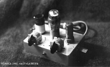
pi circuit shows the load capacitor as 2 tandom 300pf variable, but I have used even just one
300pf instead, with good results. In fact the photo shows that particular version.
Both stages are parallel fed at the plate, and are simultaneously keyed in the cathode circuit. Some versions of this transmitter will include a 150mA d.c. milliammeter, or a 6-8 v. pilot lamp (#46 pilot) in the B+ circuit to the 6L6GC plate. No parasitic choke supressors are needed.
Using the components which I describe, your power supply should be able to deliver under load at least 300v d.c., although I have run as high as 400v.
Return to top
Some Construction Notes
I recommend the use of an aluminum chassis for this project. It can be built on an open breadboard,
but unlike a single tube transmitter, there are a lot of components and high voltage lines at large
which will be safer if put under chassis and out of operating reach. While I have built this
project on a 4"by 5" chassis before, I suggest a 5"x 7" chassis.
You might note the crystal on the side- this particular transmitter coupled with a BC-453/converter, and the position for that crystal was handy. Otherwise, I would have put it on the top, like an Ameco AC-1. You might also build this rig into a metal cabinet, to minimise TVI.
While I am a proponent of outboard power supplies with receivers, not so with transmitters. But the use of a very small chassis may force you to build a separate P.S., which could be used for other projects as well. A larger chassis will accommodate a transformer and electrolytic caps. Of course, the photo shows a small version, and the PS can be seen in the main page photo.
Return to top
Winding the Coils
The coil link basically shows an inverted plastic film canistre with coil wrapped around it.
You can use B&W coil stock, Air Dux, whatever you have that's close. On my original, which
I largely used on 40m, I got by with around 20 turns of something like #22 magnet wire. You
can wind around 30 and use a tap like the schematic shows as well. You will need to experiment
a bit, a lot is determined by the value of those variables on either side, the plate tune and
antenna load.
Return to top
Set-up and Operation
Making this transmitter talk is not complex, although it is a bit more involved that your
solid state autotuned punch-and-go ricebox. Yes, you must turn knobs. But hang in there, friend,
we'll get through this together.
To set it up, we must make sure the amp output has a load to toss all that whopping 30-40 watts into. Traditionally, we used to use a lightbulb. The technocrats might be appalled at this suggestion, but for us, it sure beat trying to come up with a non-inductive 50 watt resistor when all you have is a bike and you live in Goldenrod, Florida in the early 1970's. Could just have well been the 1930's. We could only get to the Big City twice a month (until you could get your own car at age 17). It was a whole lot cheaper just to go to the SuperX, and get a sixty watt bulb.
After soldering or bolting a length of coax to the bulb socket and screwing in the bulb, plug in your 40 or 80 m. crystal and turn the supply on, making sure your key isn't closed. Position the Plate and Load caps to mid position. The first thing you want to do is get the plate tank resonant, to give the power a place to develop (this begins to give the final tube a place other than itself to dissipate the power being generated).
Key down, and quickly rotate the plate tune cap until you see the lightbulb begin to light. You don't want to hold the key down really long for this, but you can't turn the variable too fast either at this point, because the lamp will not be very bright. The antenna load will bring the bulb to brightness in the next step. For now, find the point where the lamp begins to glow, and set that plate tuning cap where the lamp is the least dim ( most bright.)
Next, rotate the antenna loading cap until the bulb reaches maximum brightness. When you have found that point, go back to the Plate tune, and re-peak ( the reactance of the antenna circuit will have altered your tank tuning just a bit ) to maximum brightness. Re peak the antenna (load) cap again, and you should have a pretty fair light on a 60 watt bulb. If you use a 40 watt bulb, it will be fully bright. If you use a 20 watt bulb, then PPFFFFTT!! :>)
I suggest that you get an SWR metre just as soon as you can. It is well worth the money, and it is great to keep in line with the antenna on this rig. Not to hang you up on perfect antenna matches, no . . . far from that. But in the forward position, it's a cheap and dirty way to peak your little MOPA into that fantastic dipole I just know you are already making !! And it is convenient to have an idea what your standing wave is, although these little rigs can really take a pounding. Not to encourage abuse or anything, but the reason why I like the 6L6 or the 6V6 (the lower powered version of the 6L6)is because it can handle rough treatment.
Before we had an SWR metre, (meter . . .I went to grammar school in europe. I still get the spellings mixed up) our little group of novice solderheads used a little trick from the 1930's: a flashlight bulb and a 1.25 inch diametre 2 or 3 turn loop of wire. The bulb was soldered across the coil, and the coil was placed near the tank, and when resonant, the bulb would glow.
So, after you have the rig peaked with the 40 or 60 watt bulb, connect your antenna coax or balance line, (i use coax, myself) and either put your SWR meter in line with the antenna, or get your tuning loop and bulb ready. Key the rig and retune firstly the plate to max output. Then the antenna.
WAITAMINNIT! What about the dippin' and peakin' and stuff??
Well, friend, you just did all that. I hear lots of folks new to tube rigs get caught up in the dipping and peaking thing (sounds like the chicken polka, kinda, ja?) so I think a little discussion is appropriate here. ( You grizzled vets can tune out here and go back to the 60wpm traffic net.)
We are not reading current on this rig, which you, of course could if you wanted to. Milliammetres were expensive luxuries to us, and we learned to do without them. These rigs operate well into the safe range of tolerances, so i just opt to make MOPAs without them.
When you peak the plate tank with the bulb, you are causing the final tube to see a load, which causes less current to flow, and the mA metre will drop from, say, 120mA to 40mA. Not much power when you are in the 300v range (300 x 0.040 = 12 watts) but when you begin to tune the antenna, more current flows, and more power develops. The change in reactance in this circuit due to the antenna tuning effects will detune the plate slightly, so you go back and re-tune, which in essence, "re-dips" the current, only less, say, to 70mA instead of 40mA. This, in turn, will slightly de-tune the antenna, so you re-peak it. Current goes up (maybe to 115mA). Now, re-tune re-dip) the plate, and it will only dip to around 100mA. Re-peak the antenna, and when you go back to the plate, hardly, or any retuning is required.
Now, if we had a tuned input to the final, we would have detuned it, too, which would require us to re-peak the grid circuit, but we don't have that, so tuning is confined to the output tank only.
This sounds complex and really time consuming, but it isn't. After you get to know your transmitter, it is no different than shifting that double-clutching '52 F-100 pickemup truck. Tuning is so easy these days on the rice boxes that I feel wierd doing nothing. 'T'aint right.
Return to top
Some Added Comments
A word about the antenna. I would use a resonant halfwave center-fed dipole for 40 or 80m.
One reason is harmonic radiation. When these sets were cutting edge, there were no TVI issues
to contend with. Using a random wire is fine, but I would spend the extra dough for a matchbox
or at least an "L" single wire tuning circuit. They are easy to build from Junque box parts,
and can be a handy thing to have. In the future, I will post the circuit.
When this rig is not tuned to resonance, a lot of current is flowing, placing a large load
on the power supply. As a result, keying characteristics will suffer, and you might find yourself
chirping like a jay with it's tail a'fire. ALWAYS MONITOR YOUR KEYING WITH YOUR RECEIVER, OR
SOME MONITORING DEVICE. Even a regen, built in a metal container like an old lunch pail will do.
They used these "growlers" in the 1920s, and for simply monitoring the sound of your rig, they
weren't bad at all. These days, I would use that nice receiver (you did get a decent receiver,
didn't you?) to monitor, really. Much as I like regens, and use them in cw QSOs, I feel much
more comfortable knowing I probably will not get a citation as long as I can hear what the FCC
is hearing. Once I have the rig tuned, and know it's doing fine, then I don't worry about it
after that.
Have a blast!
Return to top
A Brief Summary
Well, here we are. I think you will like the "Late '40s MOPA" as much as I have over the years.
The name I chose is really not entirely accurate because these rigs have been built ever since
the mid 1930's, and have been featured in QST and CQ and 73 and countless other publications
clear up into the 1980s. And beyond that time as nostalgia articles. But in my mind, the peak
time of use was during the Surplus Boom of the late '40's and the introduction of the Novice license
class in the early '50s. These rigs are not much more complex to build than the single tube
tri-tet, of pre-war fame, and far easier to tune and fly. Much more stable and a more
efficient use of energy, in my experience.
Once up and running the way you like it, it can do an amazing job! 35-40 watts is nothing to sneeze at, especially on 40 meters. With a 1/4 wave vertical and an NC-303 receiver, I can work just about anybody I hear. It's kinda hard to compete with a kilowatt, but remember, a 120 watt signal will barely produce two S-unit greater signal (doubling power roughly produces a 3 db increase). Don't let the watts fool you.
A fun thing to do with rigs like these is to pair them off with different vintage receivers. My favourite fun-time rig is this MOPA coupled to a BC-453/converter. What a neat pair they make. Or the Regenerodyne featured on this site. Perfect match!
Return to top
A Suggested Power Supply
The link above will take you to a schematic of a power supply design that I have used for many
years, a very standard non regulated unit designed for "lower" power transmitters. The rectifier
tube has two plates, so it is wired as a full wave rectifier. Keep in mind
that what is considered "low" power in tube construction is not necessarily QRP, and voltages
are lethal. The resistance of skin breaks down at about 70 mA under the pressure of
voltages as low as 40 (so I hear. . . . I never really tested it.) so you need to be careful.
Your place is with the living.
The transformer should be capable of delivering about 350v either side of center tap to the tune of 120 mA, although this set-up will work with any voltage. Just make sure the voltage rating of your filter caps (electrolytic capacitors) are safely above your output voltage. Here's what I mean:
When your rectifier tube forces a pulsating d.c. voltage across those caps and through that filter choke, those caps charge up and discharge when the pulsating d.c. reaches the '0' voltage node. This is how it 'smoothes' out the rippling d.c., or 'filters' it. But in that process, the discharge effectively contributes to the overall voltage, and when you measure the resulting filtered d.c., you will find it to be actually more than the transformer output. Instead of 350v as in the above transformer output, your VTVM or VOM might read 400v! Yessir, that's real volts. And it is for this reason you need to insure your filter caps' voltage rating is well above your transformer's rated output. In our case, 20 to 40 mF at the working voltage of 450 will do. Under load, the voltage will drop some, but with our mid-powered transmitter, not all that much. I must note at this point that your tube rectifier will have it's own voltage drop, especially the 5U4GT I use in the schematic. The 5Y3GT will too. The mercury vapour rectifiers will have much less, and will serve as a type of regulator. Get the pin-out and specs for the rectifier you choose to use from an old ARRL handbook, or from the net. The 5U4 pin out is: pin 4 and 6 are the two plates, 8 and 2 is the filament (5.0v).
That 20k 20w. resistor is there for 2 reasons: to bleed off the charge on the filter caps after you shut the thing off, and to present the supply with a load of sorts. A little bit of load on the supply tends to produce a little bit of regulation, especially when combined with the filter choke. This means that as the current demand increases and decreases as you key the transmitter, the resulting voltage drop (called EI drop, or current and resulting voltage drop) will tend to remain somewhat stable, although nothing like a regular regulated supply. There will be a simple regulated supply project coming up soon, but for lower powered cw rigs, this will do.
Use common sense when routing your power cables, if you build this supply in an outboard chassis. Use a three-conductor cable and female plugs (cinch-jones, tube socket and shell casing, or at least run the cable through a grommeted hole in the transmitter chassis and directly wire it in) to prevent accidental contact with any high voltage leads. You can, of course, build the supply right on the same chassis as the transmitter.
That filter choke is a good thing to have, but sometimes a hard beast to find. If you absolutely run into a brick wall in it's procurement, you can omit it, and just use the two filter caps. If you do this, be especially aware of the voltage tolerances of those caps because there will be no voltage drop across a choke, and you will see a higher output voltage. You may want to order 600v caps from Antique Electronics Supply, or wherever you plan to get them (I use milsurp caps). One last word about the filter choke: I chose 8 henries because I had it handy. You can use more but I would try not to use less. And make sure the current rating is greater than your output current. I use a 200mA choke.
Note the fuse in the primary side of the transformer. Use one that is rated at 120v and at least 400 mA, although to be honest, I sometimes use higher current ratings. If a short in the rig causes a massive current draw, even a 1 amp fuse will blow and shut down the rig. But I am a big believer in tripping off the system if the current doubles. If you suddenly draw 250 mA with this transmitter, something is wrong, and that transformer will cook itself quickly. Point is, fuse your little treasure to protect it and you.