Sharp
LQ6NC02 Color TFT LCD
 This page is for those who want to
power up this inexpensive LCD
video monitor.
The bare display is available from
WWW.EIO.COM for $99. You do
need to supply a few DC power supply voltages and an interface
to the ribbon connector. The EIO folks have a few different ways
this can be done. Some seemed expensive and others seem to time
consuming so I set out to make a single PC Board that would supply
the 12, 5,-8 and 900 volts needed to fire up the display. What
I came up with is a single board that mounts to the back of the
monitor and in addition to supplying power it also brakes out
the control pots so you can if you wish add them to you front
panel. It also brakes out the RGB input and its control as well
as the h/v drive outs. One feature I added was the capability
to add an electronic high input impedance A/B switch option using
a MAXIM IC chip. What I am offering here is an etched , drilled
,tinned and plated through G10 epoxy glass circuit board (you
do have to cut the hole for the ribbon cable). And a limited supply
of the -9 volt DC power module needed for this project.Because
I do not make the boards (I just design it) I will have to wait
for an order of eight of them before I have the made. E-mail me
for more info. The neg 9 volt power modules will go for $10 each
, only sold with the boards! With the board you will get a schematic
and layout so you can assemble it. All of the parts are available
from Digi-key for around $30 except the -9 volt module and maybe
the MAXIM A/B chip.
BOARDS IN STOCK
!!!
This page is for those who want to
power up this inexpensive LCD
video monitor.
The bare display is available from
WWW.EIO.COM for $99. You do
need to supply a few DC power supply voltages and an interface
to the ribbon connector. The EIO folks have a few different ways
this can be done. Some seemed expensive and others seem to time
consuming so I set out to make a single PC Board that would supply
the 12, 5,-8 and 900 volts needed to fire up the display. What
I came up with is a single board that mounts to the back of the
monitor and in addition to supplying power it also brakes out
the control pots so you can if you wish add them to you front
panel. It also brakes out the RGB input and its control as well
as the h/v drive outs. One feature I added was the capability
to add an electronic high input impedance A/B switch option using
a MAXIM IC chip. What I am offering here is an etched , drilled
,tinned and plated through G10 epoxy glass circuit board (you
do have to cut the hole for the ribbon cable). And a limited supply
of the -9 volt DC power module needed for this project.Because
I do not make the boards (I just design it) I will have to wait
for an order of eight of them before I have the made. E-mail me
for more info. The neg 9 volt power modules will go for $10 each
, only sold with the boards! With the board you will get a schematic
and layout so you can assemble it. All of the parts are available
from Digi-key for around $30 except the -9 volt module and maybe
the MAXIM A/B chip.
BOARDS IN STOCK
!!!
 This is a pic of the PC boards CAD
drawing, click on it for a bigger one.
This is a pic of the PC boards CAD
drawing, click on it for a bigger one.
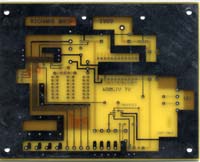 This is a bank board just as you will
get it, note the lack of the ribbon hole.
This is a bank board just as you will
get it, note the lack of the ribbon hole.
 A finished PCB mounted on the back
of the display, note the ribbon hole.
A finished PCB mounted on the back
of the display, note the ribbon hole.
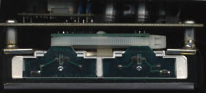 This is a side shot from the high voltage
end, note the stand offs soldered to the panel and how the high
voltage module (upper left of photo) is soldered above the PCB.
If you click on the pics you will get
a larger but slower image, use your back button to get back to
this page.As you can see the board is made to mount directly on
the back of the display. This is accomplished by attaching 4 half
inch 6-32 tapped tin plated brass spacers to the blank circuit
board with 4 6-32 x 1/4 inch machine screws( the heads can be
seen in the corners of the finished pic) these holes can be seen
in the blank PCB pics corners. Next take the bare LCD and bend
the high voltage plug leads and the black plastic spacer strait
up right at the edge of the plugs PCB so they stick strait up,
this will connect the high voltage from the PCB to the cold cathode
lamps. Next place the board and spacers on the LCD module so the
spacers line up with the holes in the tin cover on the back of
the bare LCD panel and make sure the HIGH voltage connector lugs
line up with the holes in the PCB labeled "HV" but do
not solder them yet! now vary carefully and quickly so you do
not melt the display moduals plastic solder the spacers to the
tin cover, use a large gun or big iron for this , you want a lot
of heat for a short time to do this right. Now remove the machine
screws and take the board off the LCD panel, now set the panel
aside.
Now to prep the board for parts installation.
Locate the section of the blank board that the ribbon will have
to pass through , this is vary odveous in the finished PCB pic
and can be seen in the blank PCB pic as the small rectangle in
the lower left side and can be seen in the CAD pic in the same
location. Use this etched out rectangle as a guide to cut out
the hole for the ribbon cable , cut it out using a Dremmal or
similar tool and a file to get the edges smoothed out. If you
have done all this correctly you can dry fit the board back on
the LCD panel and the hole will line up with the ribbon connector
on the panel.
Now it is time to fill the board with
parts. There is no specific order you must follow but I like to
go with the smallest parts first and I would recommend the first
part to be soldered be the 1mm ribbon connector on the PCB, It
is the most difficult part to line up and is easiest done with
out any thing in the way. This connector can not be seen in the
photos because the ribbon is in the way. I will put an arrow pointing
to it on the large pic of the blank board. This connector will
be oriented with its open end to the top for the board and the
solder tabs towd the bottom. In addition to the connection tabs
there are two tabs for holding the connector mechanically in place
these are located one at each end and after you line up the electrical
connections and solder them you can solder these machanincal lugs
to the ground foil for support. Please note that pin #1 (if you
count from left to right on the PCB with it oriented as the photos
have it , pin 1 is left& 20 is right ) Is soldered to the
ground foil ,so use pin #20 to line up the connector with all
the pins . make sure this is as perfect as you can get it these
contacts are 1mm spaced and you will have to use a small low wattage
soldering iron to make these joints. If you are not good at soldering
get some one who is to do this component ,it is the most difficult
of the project. follow the parts lay out that comes with the board
for the rest of the parts, it is a breeze , just like the old
heath kits. If you do not need the A/B video switch you can put
a jumper on the board and it will be a one input unit .You do
not have to use the external pots if you do not wish to or you
can use just the ones you need . You do not have to use the RGB
ins or hook up its control if you do not need it , it was put
on the board encase some one would need it.
Now for testing .If all is correct
place the now complete board on a non conductive surface and hook
up a 13.8 volt dc power supply to the ground foil and the +DC
input of the board. BE CAREFUL THE HIGH VOLTAGE MODULE WILL DELIVER
900 VOLTS AT 5ma AND CAN HURT OR KILL YOU IF YOU TOUCH IT!!!!
With a good digital DMM check the output of the 5volt regulator
and the 12 volt regulator. If all is correct now VARY carefully
check the output of the HIGH VOLTAGE section by measuring betrween
the ground foil and each one of the two high voltage outputs it
should be near 900 volts AC.The last supply to check is the negative
eight volt supply, if you bought a HALO module from me or another
source you know it puts out -9 volts but I placed a diode in series
with this module so we will get a 0.7 to 0.9 volt drop across
the diode giving us 8.1volts to 8.3 volts , this is close enough
to work fine but you must put a small load on it to check it .Use
a 1k ohm resistor for this. If you really want to be safe you
can check to make sure all the voltages make it to the correct
pins of the twenty pin connector so you do not blow up the display!!!
Now for final assembly and check out.
Put the long 20 pin 1mm ribbon cable you get from Digi-Key in
the module instead of the short one , note which way the contacts
face, Insulated side facing the barcode.Place the completed PCB
on the prepped display module , run the ribbon through the hole
in the board you cut earlier and screw down the PCB using the
6-32 machine screw, once again be sure the high voltage leads
line up with the holes. Now carefully put the other end of the
20 pin ribbon cable in the connector on the PCB note the insulated
side is on the board side and the contact side faces up, you should
not have to twist the ribbon. Now solder the four HIGH VOLTAGE
leads to the PCB.You can now test the assembly by hooking it up
to the 13.8 volt power supply and the first thing you should see
is the cold cathode back lite come on , if it dose not check your
work again. Now put video into the appropriate input and you should
see it on the display!! You will note at this point you do not
have any control of the image. If you want or need such control
just add the pots needed and all should work fine. Good luck and
enjoy the new toy.
This is a side shot from the high voltage
end, note the stand offs soldered to the panel and how the high
voltage module (upper left of photo) is soldered above the PCB.
If you click on the pics you will get
a larger but slower image, use your back button to get back to
this page.As you can see the board is made to mount directly on
the back of the display. This is accomplished by attaching 4 half
inch 6-32 tapped tin plated brass spacers to the blank circuit
board with 4 6-32 x 1/4 inch machine screws( the heads can be
seen in the corners of the finished pic) these holes can be seen
in the blank PCB pics corners. Next take the bare LCD and bend
the high voltage plug leads and the black plastic spacer strait
up right at the edge of the plugs PCB so they stick strait up,
this will connect the high voltage from the PCB to the cold cathode
lamps. Next place the board and spacers on the LCD module so the
spacers line up with the holes in the tin cover on the back of
the bare LCD panel and make sure the HIGH voltage connector lugs
line up with the holes in the PCB labeled "HV" but do
not solder them yet! now vary carefully and quickly so you do
not melt the display moduals plastic solder the spacers to the
tin cover, use a large gun or big iron for this , you want a lot
of heat for a short time to do this right. Now remove the machine
screws and take the board off the LCD panel, now set the panel
aside.
Now to prep the board for parts installation.
Locate the section of the blank board that the ribbon will have
to pass through , this is vary odveous in the finished PCB pic
and can be seen in the blank PCB pic as the small rectangle in
the lower left side and can be seen in the CAD pic in the same
location. Use this etched out rectangle as a guide to cut out
the hole for the ribbon cable , cut it out using a Dremmal or
similar tool and a file to get the edges smoothed out. If you
have done all this correctly you can dry fit the board back on
the LCD panel and the hole will line up with the ribbon connector
on the panel.
Now it is time to fill the board with
parts. There is no specific order you must follow but I like to
go with the smallest parts first and I would recommend the first
part to be soldered be the 1mm ribbon connector on the PCB, It
is the most difficult part to line up and is easiest done with
out any thing in the way. This connector can not be seen in the
photos because the ribbon is in the way. I will put an arrow pointing
to it on the large pic of the blank board. This connector will
be oriented with its open end to the top for the board and the
solder tabs towd the bottom. In addition to the connection tabs
there are two tabs for holding the connector mechanically in place
these are located one at each end and after you line up the electrical
connections and solder them you can solder these machanincal lugs
to the ground foil for support. Please note that pin #1 (if you
count from left to right on the PCB with it oriented as the photos
have it , pin 1 is left& 20 is right ) Is soldered to the
ground foil ,so use pin #20 to line up the connector with all
the pins . make sure this is as perfect as you can get it these
contacts are 1mm spaced and you will have to use a small low wattage
soldering iron to make these joints. If you are not good at soldering
get some one who is to do this component ,it is the most difficult
of the project. follow the parts lay out that comes with the board
for the rest of the parts, it is a breeze , just like the old
heath kits. If you do not need the A/B video switch you can put
a jumper on the board and it will be a one input unit .You do
not have to use the external pots if you do not wish to or you
can use just the ones you need . You do not have to use the RGB
ins or hook up its control if you do not need it , it was put
on the board encase some one would need it.
Now for testing .If all is correct
place the now complete board on a non conductive surface and hook
up a 13.8 volt dc power supply to the ground foil and the +DC
input of the board. BE CAREFUL THE HIGH VOLTAGE MODULE WILL DELIVER
900 VOLTS AT 5ma AND CAN HURT OR KILL YOU IF YOU TOUCH IT!!!!
With a good digital DMM check the output of the 5volt regulator
and the 12 volt regulator. If all is correct now VARY carefully
check the output of the HIGH VOLTAGE section by measuring betrween
the ground foil and each one of the two high voltage outputs it
should be near 900 volts AC.The last supply to check is the negative
eight volt supply, if you bought a HALO module from me or another
source you know it puts out -9 volts but I placed a diode in series
with this module so we will get a 0.7 to 0.9 volt drop across
the diode giving us 8.1volts to 8.3 volts , this is close enough
to work fine but you must put a small load on it to check it .Use
a 1k ohm resistor for this. If you really want to be safe you
can check to make sure all the voltages make it to the correct
pins of the twenty pin connector so you do not blow up the display!!!
Now for final assembly and check out.
Put the long 20 pin 1mm ribbon cable you get from Digi-Key in
the module instead of the short one , note which way the contacts
face, Insulated side facing the barcode.Place the completed PCB
on the prepped display module , run the ribbon through the hole
in the board you cut earlier and screw down the PCB using the
6-32 machine screw, once again be sure the high voltage leads
line up with the holes. Now carefully put the other end of the
20 pin ribbon cable in the connector on the PCB note the insulated
side is on the board side and the contact side faces up, you should
not have to twist the ribbon. Now solder the four HIGH VOLTAGE
leads to the PCB.You can now test the assembly by hooking it up
to the 13.8 volt power supply and the first thing you should see
is the cold cathode back lite come on , if it dose not check your
work again. Now put video into the appropriate input and you should
see it on the display!! You will note at this point you do not
have any control of the image. If you want or need such control
just add the pots needed and all should work fine. Good luck and
enjoy the new toy.
 forgive the mis-spellings this page
is under construction
please note the mirror sites!!!
forgive the mis-spellings this page
is under construction
please note the mirror sites!!!
 FRONT
FRONT DOOR
Mirror#1 Mirror#2
PARTS LIST
DOOR
Mirror#1 Mirror#2
PARTS LIST


