 Well, Jim Kortge, K8IQY designed this great radio and lots of QRP-L-ers are working on it. Bob
Hightower, KI7MN, came up with a board kit. Jim used a construction technique called
"Manhattan" construction to build the rig, so the board kit is a little odd. Basically,
it's a piece of copperclad with the parts locations screened on it - no holes, no etching.
Bob also included some strips of copperclad to make the little pads (officially to be
made with an Adel nibbler, but as usual, I had to cheat.)
Well, Jim Kortge, K8IQY designed this great radio and lots of QRP-L-ers are working on it. Bob
Hightower, KI7MN, came up with a board kit. Jim used a construction technique called
"Manhattan" construction to build the rig, so the board kit is a little odd. Basically,
it's a piece of copperclad with the parts locations screened on it - no holes, no etching.
Bob also included some strips of copperclad to make the little pads (officially to be
made with an Adel nibbler, but as usual, I had to cheat.)
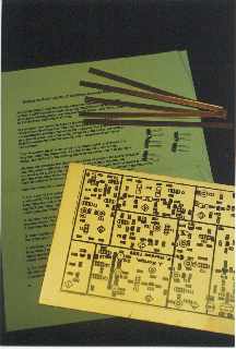
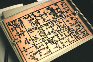
In addition, Chuck Adams, K5FO, matched some sets of crystals and donated them to be sold with the board kits. This project was to support the Arizona sQRPions. The KI7MN kit is shown at right.
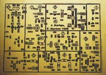
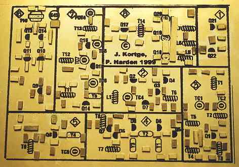
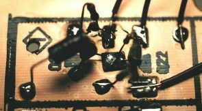
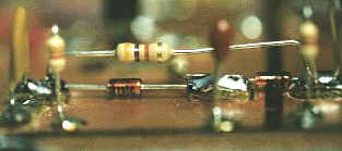
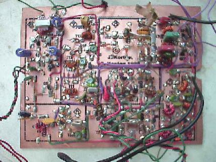
At the left is a picture of the board. The rig involves 22 transistors, all 2N2222's. The radio is constructed by wiring between pads glued to the copperclad with cyanoacrylate glue.
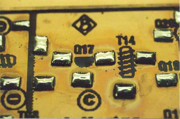
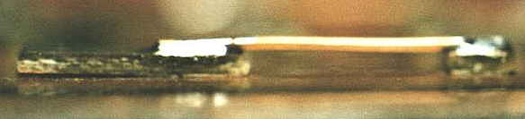
Below is a closeup of the pads glued to the board. I didn't make the pads the 'official' way. For most of the pads, the strips Bob sent were just the right size I could hack off a pad with a tin snips. OK, ok, they're all not exactly as uniform and pretty as Jim's, but hey, this is supposed to be homebrew.
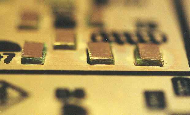
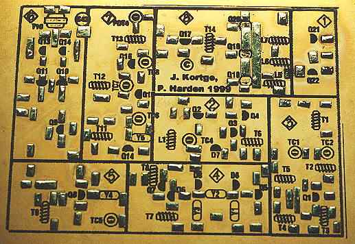
The first step is to glue all the pads to the board. Since I don't have all the parts yet, I can go ahead and do this without being tempted to rush.
Well, even so I got a little sloppy around the PA area. Ç'est la vie.
I got a little concerned about peeling the glue when trying to solder to those pads, and also wondered whether I had gotten cyanoacrylate on top of the pads - it's clear so you wouldn't see it.
Seemed logical to tin the pads - this let me discover how sloppy I had gotten with the glue, and satisfied me that the pads would be solderable when I was trying to attach a toroid.
Well, now a little wait for parts. As I progress, I'll try to record what I do and report the results here.
One of the first parts to arrive was the case. This was a good thing since it made me realize I probably wanted to fit the board to the case, drill mounting holes, etc. before I had the board filled with parts.
As you can see, it's a fairly tight fit.
The first part Jim recommends you construct is the Rx/Tx driver circuit. This is pretty simple, as you can see, and fairly easy to test. It's a simple switch, when you ground the key line, the transmit line goes high.
Now on to the VFO. This was a little more challenging, complicated by the fact that I didn't yet have the T7 toroid, which had to be ordered separate from everything else. I recalculated the toroid for a -2 core.
Apparently my calculations were wrong, because when I applied power, I couldn't find an oscillation. Eventually I discovered it way low in frequency, but after a few cycles of desoldering, remove turns, resolder, test I finally got it to oscillate in the right place.
And here's another view of the VFO which gives you a little
better idea of just how tight it can get in there.
 Oh yes, here's a picture of the cute ten-turn pot I found
at the Midland Swap.
Oh yes, here's a picture of the cute ten-turn pot I found
at the Midland Swap.

Next is the receiver front end. Pretty straightforward, although I took a break in the middle and skipped some parts. Took me a while to figure out what was going on.
The crystal filter proved to be a little more of a challenge than it looked. Perhaps I was getting a bit cocky and didn't plan things out as well as I should, but it seemed awfully tight for as few parts as were there. I was also right up against the edge of the board, and fighting with the front panel controls for air.
I was sort of surprised when I went through all my pictures that I didn't have entire views of these pieces. There were a couple of interesting details, however.
 You really need to plan out just how you are going to lay out
the parts for each section before you start. Bob's boards outline
the major parts, and Jim's page has placement diagrams for all the
parts, but they are 2 dimensional. They don't tell you that once
the crystal is soldered in you won't be able to get at that transistor,
or that the resistor has to go over the diodes.
You really need to plan out just how you are going to lay out
the parts for each section before you start. Bob's boards outline
the major parts, and Jim's page has placement diagrams for all the
parts, but they are 2 dimensional. They don't tell you that once
the crystal is soldered in you won't be able to get at that transistor,
or that the resistor has to go over the diodes.
I also found in a few places, this one in the audio amp, that there were
jumpers short enough that it was hard to strip the ends off the wire
and leave insulation between. Here I opted for thick bare wire and
relied on the height of the pads to keep it away from ground. Well,
I got squeamish when I saw it so I painted the copperclad underneath
with clear nail polish just in case.
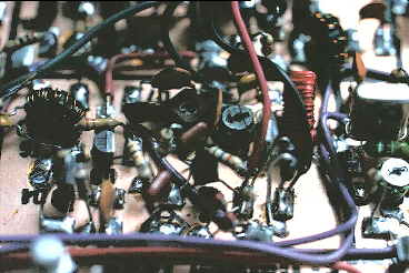
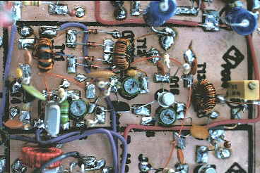
Well, things get a tad tight in around the transmit
local oscillator and mixer.
It got especailly bad when I discovered I was lacking a jumper.
At this point, I wasn't being quite so careful about checking
the parts diagram aganst the schematic. Several times I thought
Jim was wrong but after some emails, I discovered he was
right after all. So this time I didn't catch a jumper that,
in fact, was missing from the diagram.
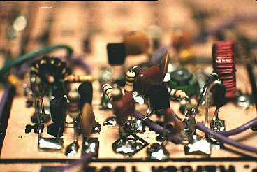
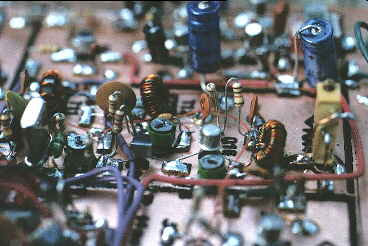
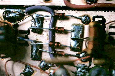
 Of course, I discover this in one of the most crowded parts
of the radio and it borders on impossible to thread the
jumper through the parts and reach way down in there with the
soldering iron! The rascal is the fine red wire toward the left
of the picture. You can also see the cermet trimmer on the right that caused
me so much grief.
Of course, I discover this in one of the most crowded parts
of the radio and it borders on impossible to thread the
jumper through the parts and reach way down in there with the
soldering iron! The rascal is the fine red wire toward the left
of the picture. You can also see the cermet trimmer on the right that caused
me so much grief.
 All I could find at first in 100 ohm was s 20 turn cermet - sort of
overkill for the purpose. Worse, it's hard to mount, and my mounting
job let go while I was tweaking up the PA. Without a ground the PA
took off and toasted the finals. Took me a while to figure out
what was going on. Oh, I knew immediately that the finals were
history, what took me a while was figuring out why. I didn't
catch the air under the ground end of the cermet.
All I could find at first in 100 ohm was s 20 turn cermet - sort of
overkill for the purpose. Worse, it's hard to mount, and my mounting
job let go while I was tweaking up the PA. Without a ground the PA
took off and toasted the finals. Took me a while to figure out
what was going on. Oh, I knew immediately that the finals were
history, what took me a while was figuring out why. I didn't
catch the air under the ground end of the cermet.
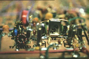
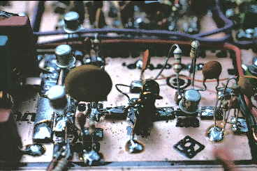 The transmit driver was a piece of cake - wide open, lots
of space. The PA was a whole 'nuther animal, however.
All I could find for the tank caps were ancient micas that
were absolutely huge. Sandwiched inbetween the toroids
there was no room to work.
The transmit driver was a piece of cake - wide open, lots
of space. The PA was a whole 'nuther animal, however.
All I could find for the tank caps were ancient micas that
were absolutely huge. Sandwiched inbetween the toroids
there was no room to work.
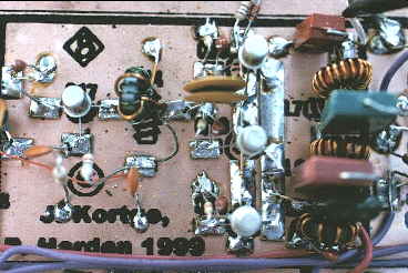 But, eventually it came together, and surprisingly enough,
actually worked!
But, eventually it came together, and surprisingly enough,
actually worked!
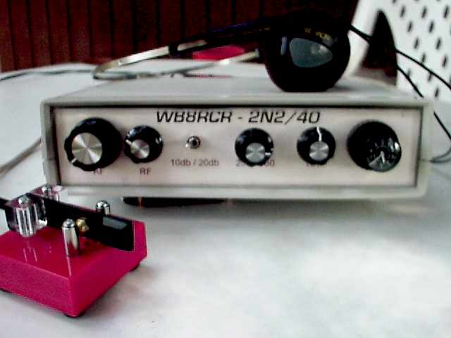
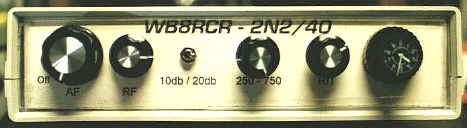 Making a decent looking panel is always a bit of a challenge.
I cheated here - I cut a piece of Plexiglas and backed it
with some glossy card stock on which I had printed the
legends. Although it's a bit of a pain to assemble and
disassemble, it's pretty servicable.
Making a decent looking panel is always a bit of a challenge.
I cheated here - I cut a piece of Plexiglas and backed it
with some glossy card stock on which I had printed the
legends. Although it's a bit of a pain to assemble and
disassemble, it's pretty servicable.
Hokay, at this point, I'm on the air. The board may be pretty usgly, but boy does this radio work nice. There is so little noise, I was convinced I didn't have enough gain, but the stations pop right out. It's smooth and really feels good. I did add the RIT board (but no pictures of it yet) which I built on regular perfboard. That turned out to be a bad move, so as soon as I get some time it's getting rebuilt Manhattan style.
I thought it might be nice to list the first few Q's. There's not a lot here because I seem to have a million things to do, and of course, I keep having to make one more tweak!