This page shows my results of taking an idea from the
G-QRP club's SPRAT magazine and making it a bit simplier for use in the
VRX-1 receiver.
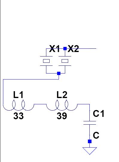
The orginal circuit used two xtals with two molded inductors. The
inductors are laid side by side on the PCB so there is ample
interaction between them. Here is the schematic:
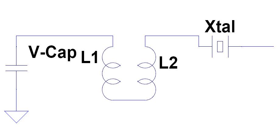
I tried this but only used one crystal and found it work rather well.
In fact, I could smoothly and with stability move the receiver's
frequency from 7.008 to 7.040 Mhz...over 40 Khz swing. "Not possible"
most would say, but it works for me. When I mounted it on the PCB that
also was used for the receiver, I found that the values of L1 and L2
needed to each be 21uh. the variable cap was one of those
from an old am 9-volt radio and measure 260pf in value.
Here is the schematic and a picture of it.
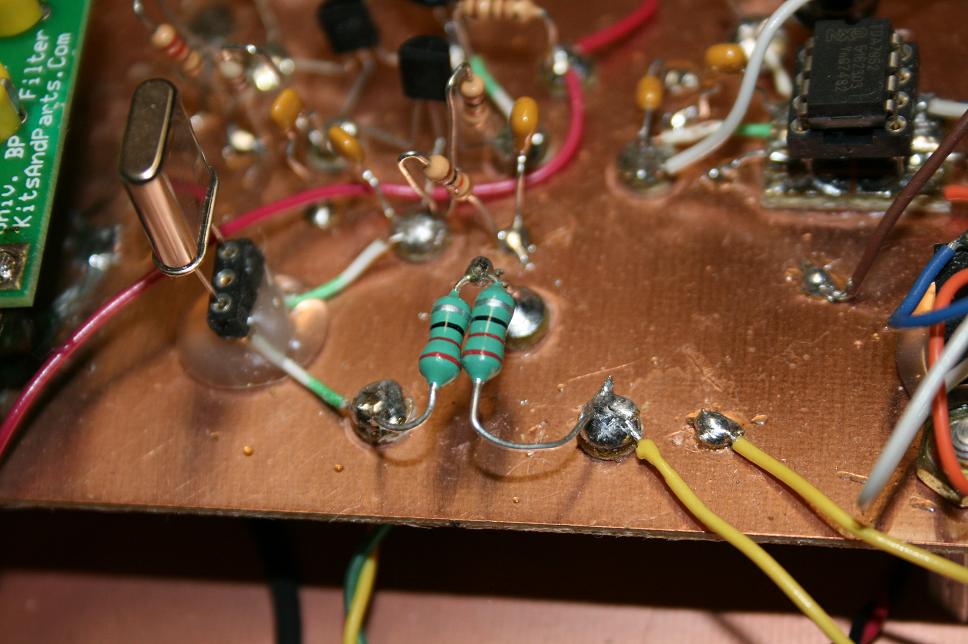
The two yellow wires are connected to the 260pf variable capacitor on
the main board. The xtal is a cheap 7.030 Mhz one I found on-line.