From: ARiazi ([email protected])
Date: Sun May 06 2001 - 09:19:52 PDT
Kal Won Kwang Wrote:
> Hi everyone,
>
> I have a simple question about modeling device R,L,C are conencted in
parallel in XTK.
>
>
> For example,
>
> (Driver) ---- (Device) ---- (Receiver)
>
>
> Equivalent circuit of above Device is as follow:
>
> ------ Resistor ------
> | |
> ------------- Inductor ------------
> | |
> ------ Capacitor -----
>
> How can I model above device in XTK?
>
> Thanks.
>
> Best Regards.
>
> Kal.
>
> #########################################################
>
Dear Kal and others:
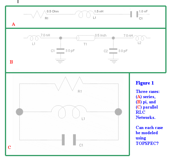
Whenever I see a question regarding XTK modeling of RLC networks, the
first thought which comes to my mind is TOPSPEC. The attachment depicts
three cases (A) series, (B) pi, and (C) your parallel RLC configuration
accompanied by the question:
Can each case be modeled via Topology Specification?
It seems to me that the answer is unanimously YES; although,
a WARNING is in order for CASE (C) due to presence of
loops. A detailed description of this modeling approach plus
results are furnished below.
TOPSPEC utilization involves defining the topology in the Model Data
Out (.mdo) file (inserted within TOPSPEC
and ENDTOPSPEC delimiters), and referencing it by the
Topology (.top) file. Use of TOPSPEC is limited to
RLC networks with only one or two ports.
The topology block can be written manually or automatically
generated using the Scratchpad (Eplanner) program. For
instance, the topology generated by the Scratchpad for
schematic of Figure 1A (representing decoupling capacitor model) is:
NET series_rlc
FORK 0.0
SERIES R1 I1 TYPE R0.5
SERIES L1 I1 TYPE L1.5NH
SERIES C1 I1 TYPE C1.0NF
ENDFORK
NEXT 0.0
ENDNET
Here the FORK, ENDFORK, and NEXT 0.0 statements
are unessential and can be deleted.
The Scrtachpad topology generated for pi network
(a connector pin model) of Figure1 B is:
NET pi_rlc
FORK 0.0
SERIES L1 I1 TYPE L7.0NH
NODE T1 X1 TYPE NOP NO_DISPLAY
FORK 0.0
NEXT 0.5 Z: 50 S: 2.0
NODE C2 I1 TYPE C3.0PF_TO_0.0
NODE T1 X2 TYPE NOP NO_DISPLAY
SERIES L2_2 I1 TYPE L7.0NH
ENDFORK
NEXT 0.0
NODE C1 I1 TYPE C3.0PF_TO_0.0
ENDFORK
NEXT 0.0
ENDNET
It is important to note that there can be more than one possible way to
describe a net topology. For example, the above pi RLC topology can
be equivalently expressed as:
NET pi_rlc
SERIES L1 I1 TYPE L7NH
NODE C1 I1 TYPE C3.0PF_TO_0.0
NEXT 0.5 Z: 50 S: 2.0
NODE C2 I1 TYPE C3.0PF_TO_0.0
SERIES L2_2 I1 TYPE L7.0NH
ENDNET
Figure 1C shows a parallel RLC, that you like to model. The Scratchpad
topology result is:
NET parallel_rlc
FORK 0.0
SERIES C1 I2 TYPE C5.0PF
NODE C1 I1 TYPE NOP NO_DISPLAY
FORK 0.0
SERIES L1 I1 TYPE L2.0NH
NODE C1 I2 TYPE NOP NO_DISPLAY
SERIES R1 I2 TYPE R1000
CONNECT_NODE C1 I1
ENDFORK
NEXT 0.0
ENDNET
To create TOPSPEC definition for above, it is necessary to replace the
NET and ENDNET with TOPSPEC and ENDTOPSPEC respectively.
It is also required to appropriately reference the topology block by
the .top file ( there exist three possible ways namely, SERIES block,
NODE block or PIN block). Here the SERIES block method is
applicable, as demonstrated below:
In the .top file:
SERIES DEVICE 1 TYPE parallel_rlc
#
In the .mdo file:
TOPSPEC parallel_rlc
FORK 0.0
SERIES C1 I2 TYPE C5.0PF
NODE C1 I1 TYPE NOP NO_DISPLAY
FORK 0.0
SERIES L1 I1 TYPE L2.0NH
NODE C1 I2 TYPE NOP NO_DISPLAY
SERIES R1 I2 TYPE R1000
CONNECT_NODE C1 I1
ENDFORK
NEXT 0.0
ENDTOPSPEC
#
LOADSPEC C5.0PF
CEFF: 5.0
#
LOADSPEC L2.0NH
LEFF: 2.0
REFF: 0.0
#
LOADSPEC R1000
REFF: 1000
#
LOADSPEC NOP
CEFF: 0
#
The LOADSPEC statements have been added for purpose of completion.
Since no values had been specified for R, L or C; I arbitrarily assigned
R = 1K, L = 2.0 nH, and C = 5.0pF . Of course, they can be readily
altered and set to any desired values.
WARNING, since above Topology block includes CONNECT_NODE (due to the
loops), some versions of XTK may reject the TOPSPEC.
When employed as a series block, TOPSPEC describes a two-port network. Port
1
(by default ) is first statement following TOPSPEC, and port 2 the last
statement prior to ENDTOPSPEC record. A series TOPSPEC can be inserted
in reverse order by use of REV keyword at end of SERIES statement (in the
.top file).
In closing, a wide variety of RLC networks can be modeled using TOPSPEC
(although there are limitations). A crucial step is construction of the
topology block,
and this can be accomplished either automatically using Scratchpad or
written manually.
When generated by the Scratchpad there may be a FORK, ENDFORK and
NEXT 0.0 statements which are unnecessary and hence removable.
Furthermore, the NET and ENDNET must be replaced by TOPSPEC and
ENDTOPSPEC respectively, then inserted in the .mdo file and properly
referenced
by the .top file. LOADSPEC statements are also usually required to complete
the
model. Some applications of TOPSPEC definition consist of
creation/incorporation of
high bandwidth XTK models of decoupling capacitors, termination resistors,
connector
and IC package pins.
I hope you find this information useful, and with best regards,
Abe Riazi
ServerWorks

**** To unsubscribe from si-list or si-list-digest: send e-mail to
[email protected]. In the BODY of message put: UNSUBSCRIBE
si-list or UNSUBSCRIBE si-list-digest, for more help, put HELP.
si-list archives are accessible at http://www.qsl.net/wb6tpu
****
This archive was generated by hypermail 2b29 : Thu Jun 21 2001 - 10:11:50 PDT