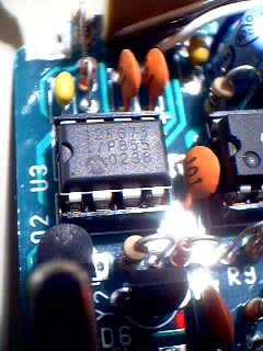
The RMK is a replacement for the Rock-Mite's supplied PIC keyer chip.
The chip kit can be ordered from Jackson Harbor Press at
http://jacksonharbor.home.att.net/ham.htm.
The first thing I recommend with the RMK is to read the instructions.
Well, ok read at least the first page. Doing this will tell you the values
of the resistors and where they need to be installed into the circuit on your Rock-Mite.
When I started on this project I knew that I wanted to mount the speed
potentiometer right on the Rock-Mite PCB... but where?
I found just the spot.
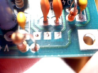
As you can see there is a trace on the top of the PCB in the spot where
I wanted to put the pot. What I did was totally unorthodox because I just
drilled holes for the pot's leads on either side of the trace with a very small bit.
I DO NOT RECOMMEND THIS UNLESS YOUR ARE CRAZY LIKE ME.
You should probably grind off the trace and replace it with a jumper
from the bottom of R8 to junction of C104 and D4 where it used to connect.
My older PCB (pre 09/02) has R8 closer to the corner so the pot
was easier to install.
Since I came dangerously close to the trace which was carrying +12v,
just for safety sake, I splashed on a coat of nail polish over the trace
befor mounting the pot.
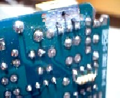
I used a small dremmil type tool to grind off the trace on the back of the PCB.
All of this area is ground (-12v). I just had to make sure I did not isolate
any connections to ground from any of the existing componants.
Next you need to mount the pot.
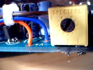
The picture above shows the pot mounted in place. I used a dab of perma-bond
on each end to hold it in place.
You can see that the board shown does not have an R8
where it is on the newer boards.
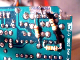
This final picture shows the pullup resistor plus the other two resistors
needed to make the whole getup work. The horizontal resistor is the pullup
resistor soldered from pin 1 to pin 4 on U3. The resistor to the left
connects the pot to ground. The resistor on the right goes from pin 1
of U3 to the pot. The center lead of the pot is connected to the 'dash'
connecton by using a short jumber. I only used shrink-wrap on one of
the resistors because it crossed over a lot of other connections.
I soldered the resistors to the back of the PCB because
I didn't want to start soldering leads to the legs of the PIC. Also,
if I ever wanted to go back to the original PIC, I would only need to change
the chip and not have to hassle with warming up the iron.
The cut corner of the PCB has nothing to do with the RMK PIC mod.
I had to do this to allow my enclosure to close.
[Home] [QSL] [QRPP] [Projects] [Links]