 CW RECEIVER FOR 80 AND 40 METERS
The easy 80 and 40 meter Simplest Ham Receiver described on this site
has proven to be (after almost 2 decades!) versatile, stable, durable and effective. However,
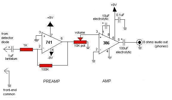
interest and curiosity has been expressed for a version with an audio amp section using integrated
circuits instead of discrete components.

 Instead of just replacing this circuit and the two power supplies for those on the existing
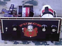
receiver, an entirely new version was built using a cigar box.
Performance is about the same as the discrete-component-amp receiver's, but with much more volume. The cigar-box version has all parts very close
together and no metal panel for the VFO section. Using headphones With my station's setup, and
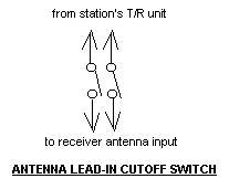
when transmitting more than about a watt, the antenna lead-in line to the receiver requires an external
cutoff switch to prevent gross overloading. (Back-to back diodes do not work.) However, when used
with transmitters running about a watt or less, the signal can be monitored comfortably without
use of a cutoff switch as long as the volume is turned all the way down. However, when using a
simple external audio amplifier and speaker no cutoff switch is needed.
Instead of just replacing this circuit and the two power supplies for those on the existing
receiver, an entirely new version was built using a cigar box.
Performance is about the same as the discrete-component-amp receiver's, but with much more volume. The cigar-box version has all parts very close
together and no metal panel for the VFO section. Using headphones With my station's setup, and
when transmitting more than about a watt, the antenna lead-in line to the receiver requires an external
cutoff switch to prevent gross overloading. (Back-to back diodes do not work.) However, when used
with transmitters running about a watt or less, the signal can be monitored comfortably without
use of a cutoff switch as long as the volume is turned all the way down. However, when using a
simple external audio amplifier and speaker no cutoff switch is needed.
The experimental cigar-box receiver was designed with several specific goals in mind: easy-to-build with as many parts from the junkbox as possible and the others readily available, using the I.C. audio amp, and to be more compact and portable ("looks like a radio...").
Construction:
The front-end coils were wound with on-hand insulated stranded hookup wire instead of enameled
("magnet") wire and the coil forms are large size vitamin bottles. Using anything but the
specified magnet wire for these coils is not prudent, but the substitution
works. Also from the junkbox came the germanium diode,
a small-value air timmer cap linking the front-end coils (substituting for a 4.7pF ceramic-disc),
RCA jack, the variable capacitors (335 pF miniatures), all the switches and all the knobs.
The lid of a 10.5" x 6.5" x 2" cigar box, removed and attached to bottom's side with small nuts and bolts, serves as the front panel (actually a slightly larger lid was used here). Holes were drilled for the other panel components as they were installed. Scissors were used to ream the holes larger to fit the variable capacitors, which are glued in the holes(!)

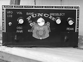


The variable capacitors C1 and C2 Peak and Preselect and the Ant jack were installed on the chassis first - then the coils were connected to them using some beneath-chassis wiring.
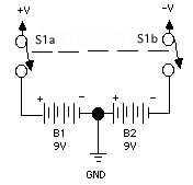
The VFO was soldered separately on its board with Band switch and Tuning potentiometer closely attached. After testing, this segment was centrally mounted with its controls on the front panel. The VFO I/O switch and Volume/Osc Pwr control (this pot has a built-in switch that serves as the oscillators' power switch) was mounted next. The VFO I/O switch is a SPST wired between the Volume/Osc Pwr control and the VFO's +V input, and permits the receiver have either, neither, or both oscillators operating. (The crystal oscillator shares the same power switch as the VFO; it stays "off" until a crystal is inserted.) Coil L2 was then repositioned to be about 1/2" from the VFO's adjustable inductors.
The audio board was then assembled separately, tested, and hooked up. IC sockets were soldered on the board to prevent possible damage to the ICs and to make their replacement easy. The slide Amp Pwr switch, battery holders, and Audio Out mono 1/4" phone jack were then installed and connected to their appropriate components. More below-deck wiring was done during this stage to reduce clutter.
After the the receiver was tested and confirmed to be working, the crystal oscillator was wired to its power switch (shared with the VFO) and installed beneath the chassis with the Xtal socket emerging in front from underneath.
Operation and Performance:
The basic circuitry is the same as the discrete-component-amp Simplest Ham Receiver's, so operation is the same.
The addition of a volume control and the VFO I/O switch gives it more versatility. It performs
very well, with a smooth "feel." The performance is about equal to the
Audio Q-Multiplier enhanced version of the Simplest Ham Receiver.
Due to its high gain, earbuds are not recommended!
A 1/4" phone-plug to 1/8" stereo-jack adapter permits stereo headphones to be used.
The need for the external antenna lead-in cutoff switch when using headphones is the receiver's biggest drawback.
 Even though there is an automatic antenna T/R switch at this station,
the cutoff switch needs to be thrown AND the volume
needs to be reduced to minimum during transmit periods when using transmitters with an output of over one watt.
(An external volume short-out switch was tried to minimize volume - it made the unit unstable.)
This is not serious; a switch has to be thrown or a knob had to be turned to reduce volume with the
Audio Q-Multiplier enhanced discrete-component-amp Simplest Ham
Receiver anyway. As shown in photo at left, the cutoff switch is housed in a plastic box;
the cables connecting the box from the T/R device to the receiver are common ones left over
from a DVD player. The cutoff switch is not needed at this station when
a simple audio amp and speaker is used instead of headphones. This simple addition makes the operation
of the receiver much easier and more pleasant.
Even though there is an automatic antenna T/R switch at this station,
the cutoff switch needs to be thrown AND the volume
needs to be reduced to minimum during transmit periods when using transmitters with an output of over one watt.
(An external volume short-out switch was tried to minimize volume - it made the unit unstable.)
This is not serious; a switch has to be thrown or a knob had to be turned to reduce volume with the
Audio Q-Multiplier enhanced discrete-component-amp Simplest Ham
Receiver anyway. As shown in photo at left, the cutoff switch is housed in a plastic box;
the cables connecting the box from the T/R device to the receiver are common ones left over
from a DVD player. The cutoff switch is not needed at this station when
a simple audio amp and speaker is used instead of headphones. This simple addition makes the operation
of the receiver much easier and more pleasant.
Less than $50 was spent on this project, but lot of parts were on-hand. If everything was purchased the total might come to over $75, which isn't bad for a 2-band receiver capable of receiving more bands if used with converters.