The MIRAGE B1016 represents the latest in 2 Meter Power Amplifiers. It incorporates features that make it the most useful and versatile amplifier available today. The B1016 has a built-in receive preamp, variable SSB delay, remote keying and complete remote control when using the optional RC-1, Remote Head. It will amplify both FM and SSB signals. It has built-in thermal protection to prevent over heating.
SPECIFICATIONS:
| FREQUENCY RANGE | 144 to 148 MHz |
| POWER | INPUT 1-15 Watts (18 Watts max.) OUTPUT 160 Watts or more for 10 Watts input intermittent duty cycle |
| MODES | FM, SSB and CW |
| RECEIVE PREAMP | 10 db gain with 2± .5 db noise figure |
| DC POWER | 13.6 VDC at 20-25 Amps nominal |
| FUSE | 35 Amps (internally mounted) |
| IMPEDANCE | 50 Ohm input and output |
| SIZE | 12" X 3" X 51/2" |
INSTALLATION:
The B1016 may be mounted by using the brackets supplied. The B1016 must have adequate ventilation around the heat sink. Use of #8 or larger wire to connect the B1016 to the battery is recommended. Use good quality 50 Ohm co-ax, between the radio and the B1016. RG-8U or the equivalent should be used between the B1016 and the antenna. The antenna should be matched, to better than 1.5:1 for best performance. SWR less than 3:1 will degrade system performance. SWR greater than 3:1 may cause damage to the amplifier voiding any warranty.Front Panel Functions:
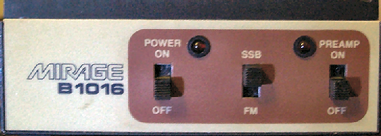
- POWER-ON/OFF-
- This switch turns the power amplifier ON and OFF.
- SSB/FM-
- Selects the relay time delay for the mode of operation. In either the SSB or FM position, the amplifier is still biased for linear operation.
- PREAMP-ON/OFF-
- Turns ON and OFF the receive preamp. This works independent from the Power ON/OFF switch. When either the Preamp or Power Amp is turned on the Amplifier automatically switches the antenna using its internal circuitry. If it is desired to key the antenna relay externally a connection is provided on the rear panel (see Rear Panel Functions).
- LED (Power On)-
- This LED will go out if the amplifier over heats. It will come back on when the amplifier has cooled.
Rear Panel Functions:
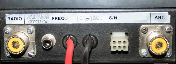
- "RADIO"-
- This connects to the transmitter or transceiver.
- "ANT"-
- This connects to the antenna.
- RCA JACK-
- This is for Remote Keying-Connect to ground to key the antenna relay.
- 6 PIN REMOTE CONNECTOR-
- The RC-1 Remote Control Head connects here.
PRECAUTIONS:
- Output Power-
- The B1016 puts out enough power to cause heating of the antenna coax. RG-8 or equivalent is recommended between the amplifier and the antenna.
- Heat Sink Temperature-
- Along with high power output comes the possibility of high heat sink temperatures. The B1016 must be mounted where air can circulate over the heat sink. The B1016 has a built in thermostat that will turn it off at 170 degrees F. The amplifier will not come back on until the temperature drops to 140 degrees F.
- Input Power-
- Input power should not exceed 15 to 18 Watts. Higher power than this may cause failure of the input transistor. This will VOID ANY WARRANTY.
Internal Adjustments:
- "SSB DELAY"-
- This allows the relay delay to be adjusted to any desired delay. Access to this adjustment is through the hole in the left side of the cover, behind the front panel. Use a small screwdriver to adjust the control.
- "INPUT" and "OUTPUT" MATCH (See Warranty).
- These are factory adjusted and do not normally require adjustment. The cover must be removed to make these adjustments. Connect an SWR meter between the radio and the input to the amplifier. Adjust the "INPUT" trimmer capacitor (marked yellow) for lowest SWR. Connect a power meter to the output and adjust the "OUTPUT" trimmer capacitor (marked green) for maximum output at minimum DC current drain.
- Preamp Tuning-
- These trimmers are factory set for the best gain and noise figure. They should not be re-adjusted unless connected to the proper equipment to set the noise figure.
- Fuse-
- A 35 Amp fuse is located under the cover on the P C Board. Should the fuse "blow", determine the cause before replacement.
IN CASE OF DIFFICULTY:
- Check for loose antenna or B+ connections.
- Check S.W.R.of antenna.
- Look for bad or lossy co-ax.
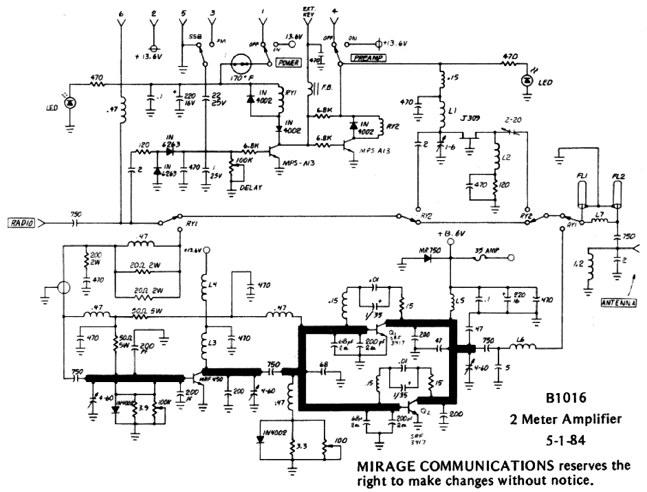
Redrawn Schematic
Corrected with values from actual unit.