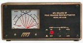
The MFJ-815B DELUXE HF PEAK READING SWR/WATTMETER
utilizes a cross-needle meter so that peak or average Foward
power, Reflected power, and SWR can be read. Foward power is in
Two ranges from 200 watts to 2000 watts. SWR is read from 1.1:1
to 5:1. Frequency range is from 1.8 to 60MHz.
Installation
- Connect the coax connector labeled TRANSMITTER to the
transmitter with RG-58/u cable. Use PL-259 connectors.
- Connect the coax connector labeled ANTENNA to the antenna with
RG-58/u cable. Use PL-259 male connector.
- If a lighted meter is desired, a 12Vdc power supply such as the
MFJ-1312B must be connected. Use a standard 2.1mm coax with the
center positive and the sleeve ground. The METER LAMP ON/OFF
switch will activate the meter lamp.
Forward & Reflected Power
- Set the desired power range by using the switch on the front
panel labeled METER HI/LOW. The high range is 2000 watts
maximum.
- The Peak Reading feature may be switched on/off by using the
push button on the front panel labeled METER PEAK/AVERAGE.
SWR Measurement
SWR is indicated by the crossing point of the two meter
pointers. While transmitting, read the SWR from the SWR line
nearest the crossing point.
- Note:
- No SWR setting is needed at any range.
Calibration
The MFJ-815B has been calibrated at the factory. If it should
ever need to be recalibrated, then follow this procedure:
Equipment Needed
- Transmitter capable of supplying enough power to obtain 1/2 to
full scale reading at 14 or 21 MHz.
- 50 ohm dummy load that is capable of handling full power that
the transmitter can put out and has better than a 1.15:1 SWR.
- A power meter of known accuracy. The calibration will only be
as good as the standard meter.
- 50 ohm cables capable of handling the power. RG-58/U is
recommended. DO NOT USE RG-59 or RG-11.
Meter Calibration-refer to PC layout for trimpot location
- Remove the top of the 815B.
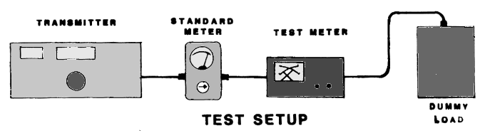
- Connect the equipment as shown in the diagram. Use 50ohm dummy
load for the antenna. Set the transmitter to 14MHz band.
- Transmit about 100 watts as indicated on the reference meter.
Adjust LOW FOWARD to set 100 watts on the foward power scale.
Next set the pushbuttons to the 2000 watt power scale. Transmit
1000 watts as indicated on the reference meter. Adjust HIGH
FOWARD to set 1000 watts on the foward scale.
- To set the reflected power, interchange the transmitter and
coax cable so that the transmitter is connected to the antenna
connector and the dummy load is connected to the transmitter
connector. Set the range switch to the 200 watt range. Transmit
10 watts as indicated on the reference meter and adjust LOW
REFLECT to indicate 10 watts on the reflected scale of the
815B. Next set the range switch to the 2000 watt scale.
Transmit 100 watts according to the reference meter and adjust
HIGH REFLECT to indicate 100 watts on the reflected scale.
- SWR requires no calibration.

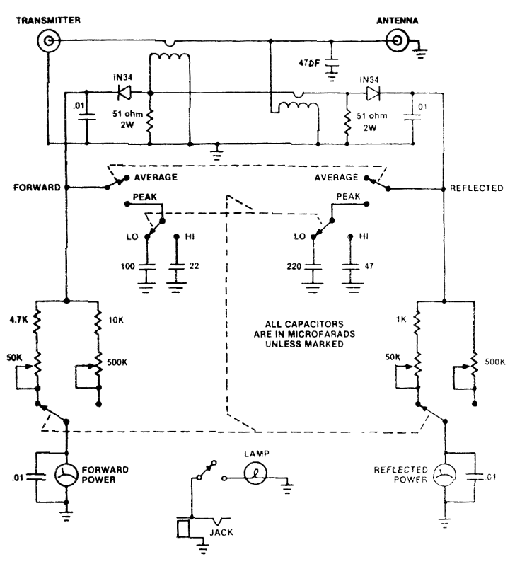
Schematic
Original manual © MFJ Enterprises, Inc.