Q. What steps should be taken before this radio is put on the air?
Check the final transistors for bad connections.
Clean the relays and add the maintenance circuit. See ASB-0902 - Low / Intermittent Receive. I added
the maintenance circuit to the back of the filter board rather than the way Kenwood describes.
Change the battery or replace it with a super cap.
Control = Replace the battery
I don't want to ever have to replace the battery again. Replace D73 with 1k resistor.
Replace battery with one of those computer battery backup high value capacitors. I used
a 1.0f (yep, one farad) @ 5.5V. Once charged the cap keeps the memories powered for
several months.
Perform some mods to improve performance: (some are optional)
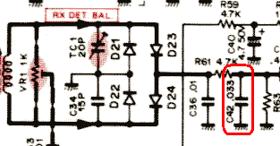
Change frequency rolloff for SSB and FM for better clarity. Change C42 to 0.003μF or 0.0047μF. FM-430 = high freq rolloff
- Change C50, 0.033μF to 0.0033μF or 0.0047μF.
- Restores high frequencies on received FM signals.
Change the noise blanker, see ASB-0887 - Noise Blanker Improvements
Change/adjust/disable the Speech Processor. Replace capacitor C104, a 4.5 μF on the IF board with a smaller value of 0.47 μF.
If needed, enable all band transmit.
If use on 60 meters, then apply 50 watt modby djb. 50 watt mod:
Control, Filter = 50W power down
(HOLD key selects 50W when pressed. Required for 60 meters.)
- Control Board: Add silicon diode (1n4148) cathode from HLD (Pin 1, conn 16),
anode to collector Q43/base Q44 connection.
- Filter: Add PWR Down components as needed as shown on schematic. L37 and R10 - one or
both may need to be added.
(On some rigs it may be necessary to remove Q43 on the control board. Q43 controls power
on 10 meters. If power on 10 meters drops to 50W after this change then Q43 needs to be
removed.)
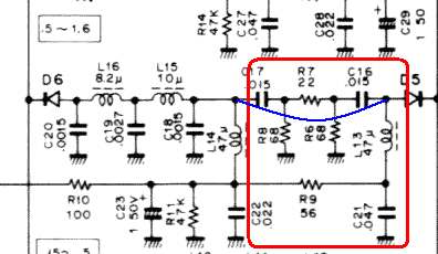
Remove attenuator on MW band. Remove C16, C17, C21, R6, R7, R8, R9 and L13. Place jumper as shown in blue.
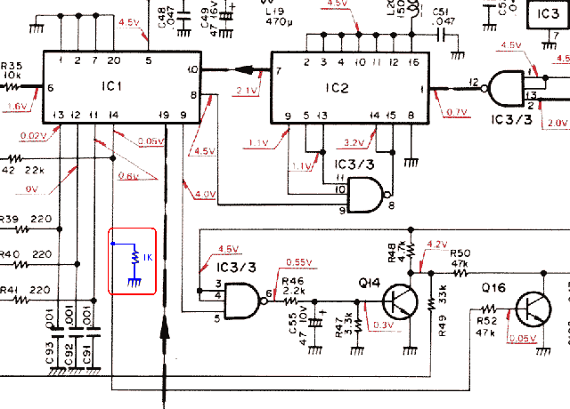
Receive below 150kHz. Add 1k ohm resistor from pin 14 of IC 1 to ground.
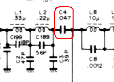
Fix the low pass filter roll off. Change C4 from 0.047μF to 0.1μF.
5 volt regulator oscillates. In both rigs, the 5V regulator, IC9 on the IF board, would break into oscillation
when the input voltage approached 12V. In the other rig, IC9 would fail around
12.5 volts affecting use of this rig mobile.
- To fix:
Add a 0.1μF @ 50V disc cap on the solder side of the board, at IC9, from the input of
IC9 to ground. Kenwood put an input cap on IC8, the 8 volt regulator, but left
the cap off the 5 volt regulator.
Sensitivity down 10db, except on FM
- To fix:
Both radios had D76 on the IF board fail. D76 is on the solder side of the IF board
and in both cases there was zero lead length on D76. Temperature changes had caused
physical stresses on D76 resulting in diode failure. I replaced D76 with a 1n4148
out of my junk box. I formed the leads of the replacement diode to allow some flex
to help reduce failure of D76 in the future.
Poor transmit performance, high IC, low power out, poor IMD.
- To fix:
The power lead to the final board had only been tack soldered -- only a few strands of
the power cable had been soldered to the final board. After all these years the
unsoldered strands had turned black. Removed, cut, stripped, tinned, and resoldered
power lead to final board.
Look for useable power switch replacments in old PC CRT monitors that have push on/push off switch.
Check alignment, adjust if necessary.
S-Meter can be adjusted to match standards (S9 == 50�v and 6db/S unit) from about S3 through 40 over S9.