Subject: TS-430S - AM Wide/Narrow filter selection
Date: December 8, 1983
This procedure will allow selection of the Wide or the Narrow filter for AM.
Parts list
Qty
Description
Circuit designation
2
2SA1115(E) Transistor
Q401, Q402
4
1S1555 Diode
D401-D404
1
4.7 Kohm 1/8 Watt
R405
2
22 Kohm 1/8 Watt
R403, R404
2
47 Kohm 1/8 Watt
R401, R402
Insulated hookup wire #28 guage or larger
1
Short jumper
Modification procedure:
Caution: This modification requires advance soldering and printed circuit board modification techniques, and should only be performed by experienced kit builders and or technicians. If you are at all unsure of your ability to install this modification after reading these instructions, please have someone with more experience perform the modification for you.
Remove the power connector from the radio.
Using a #2 Philips screwdriver, remove the top cover (8 screws). Be careful of the VOX controls, and the speaker lead, which may be unplugged.
Loosen the two countersunk side screws and remove the 2 screws securing the IF unit bracket. Swing the bracket up slightly to access and remove the two heat sink screws, Swing the assembly down.
Remove 7 screws from the IF unit. Protect the top of the front panel from scratching.
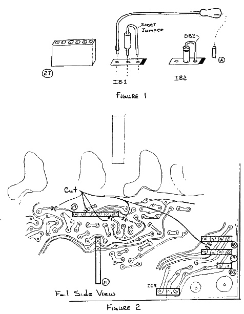
Desolder IB1 and discard (use a 45 watt or less iron, and solder wicking).
Locate the white jumper wire that is plugged on to the "S" terminal of the IF unit. Desolder the wire from its present location, and reinstall as shown in figure 1.
Install a short jumper wire, as shown in figure 1.
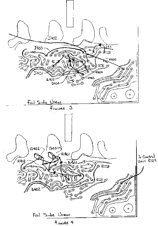
Cut the foil paths as shown in figure 2. There are five locations that must be cut. CAUTION: Ensure you cut only the traces as shown in the figure. Spend a little extra time to ensure you have correctly identified the trace to cut.
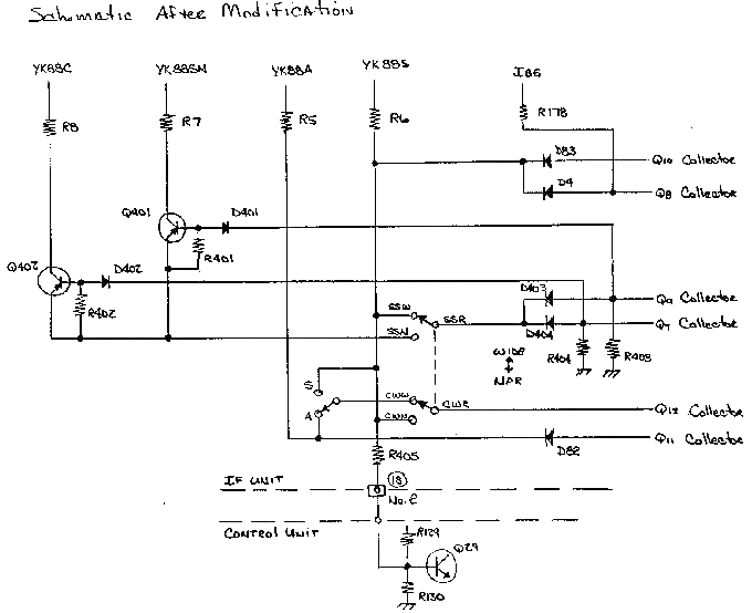
Install J401, J402 (may all ready be installed), J403, D403, D404, R403, R404, and R405 as shown in figure 2 (use the shortest lead lengths possible). Check to ensure there are no solder bridges, or splashes on the board.
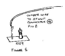
Install Q401, Q402, R401, R402, D401 and D402 as shown on figure 2, again being careful to check for solder bridges, short, etc.
Check to see if D82 is installed, as shown in figure 1. If it is not, install it (1S1555). D83 should also be installed on the foil side of the board, as shown in figure 2.
Note: Some unit's have D82 and D83 installed, if so go to step 12.
Move the filter select jumper to the "A" pin, as shown in figure 1.
On control unit (x53-1290-00), cut the lead of resistor R129.
Solder a jumper wire to the metal lead of resistor R129, as shown in figure 5. Connect the other end to IF units connector 18 pin 2 from the foil side of the board as shown in figure 4. The wire may be conveniently routed between the circuit board and the chassis.
Install insulating tape below the area of the modification to ensure that no components short out against the case.
This completes the modification procedure. The TS-430S will now select either AM Wide or Narrow. Before reassemble, go back through the procedure and check you work, to ensure no errors have been made.