Autek Research is no longer in business. This document has been created
from materials supplied with purchase.
BATTERY INSTALLATION
Obtain a standard 9 volt batterry. Use an alkaline battery for best
life. (About 12 hours of intermittent use.) Using your thumb, slide
back the battery compartment on the back. This may take some
pressure. Don't pull it up -- it slides. Install the battery without
pulling the battery leads excessively and replace the cover.
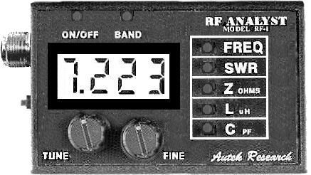
INITIAL FAMILIARIZATION
Tap the on/off switch. The first number which flashes is the
program code version, e.g. PC2.0. A higher number indicates
later software, which may reflect even a minor, unnoticeable,
change, or could even reflect a hardware change. This is the
"model number" of your unit.
When you turn the unit on it enters the FREQ mode. The "tune"
knob changes the frequency. The "fine" knob also changes the
frequency, but much slower, for bandspread when zeroing in on a
frequency.
Now tap the BAND button.The unit switches to the next of 5
bands. Now, hold down the band batten. Notice that the unit
continuously cycles between bands.
Now, tap the SWR button. An upper box appears in the left digit
showing you're in the SWR mode. but the SWR reading is "H"
meaning too HIGH to register,since nothing is cennected to the
coax connector.The "H" appears for any SWR above about 15:1.
Now, tap the Z button. The meter is now reading the impedance
of the meters stray output capacitance at the frequency in use. If
you're at a low frequency, a lower box appears in the left digit.
showing you're in the Z (IMPEDANCE) mode, and an "H"
appears in the right digit, meaning too HIGH. The "H" appears
for any impedance above 2000 ohms.
Now, change bands by tapping or holding the band button. Note
that the new frequency appears first (briefly) and then the meter
reverts back to the previous mode selected, in this case
impedance. Note that at the higher frequencies. the impedance of
the meters stray output capacitance...about 7 pf..is displayed.
More about this below.
Now, tap the 0 button. A small C appears at the lower left,
indicating the C mode. The meter will probably show a large "L" in
the right digit, meaning that the capacitance is too low to
measure.
Now, tap the L button. Instead of a small C, a small L appears in
the first digit. The right digit show "H", meaning the inductance is
too high to measure. Remember. the left digit shows you which
mode you're in, and the right digit shows any overrange,
"H=HIGH" or "L=LOW".
Now, hold down the FREQ and SWR buttons. and release them
at the same time. Notice that the meter now cycles between the
FREQ and SWFI modes. Try the same with the FREQ and C
buttons to cycle between these two modes. In fact. if you
hoid down 3 buttons, you can usually cycle between 3
modes, but more may "lock up" the computer. and you'll have
to turn the unit off/on to reset it.
BATTERY
The unit has an "automatic off" feature to save the battery. It
will automatically turn itself off after about 20 minutes of no
use--no button pushed. To disable this feature: First turn the
unit off. Then hold down the frequency button. Then tap the
on/off button. You will not see the PCx.x indication,
confirming that auto-off is disabled.
The unit is totally voltage regulated as the 9 volt battery
drops to 6.5V. Between 5.5 and 6.5V the accuracy is
degraded a few percent. At 5.5V the display dims very
noiceably as a reminder to replace the battery. The unit
draws 35~60 ma.--the most at the highest frequencies. It can
be run from any DC source 6.5 to 15 V.
IMPEDANCE MEASUREMENT
RF impedance is measured by rectifying RF voltages using
diodes. These diodes introduce errors in the measurement
which are compensated by the microprocessor software, but
not quite perfectly. In addition, even an inch of lead wire to a
resistor can produce a noticeable change in Z at the higher
frequencies!
Because of the above, a DC digital voltmeter will be more
accurate than your RF ANALYST for measuring DC values
of resistors, but is, of course, useless for measuring RF
impedance.
Figure 1 shows impedance accuracy. Note that
accuracy is best near 150 ohms, and degrades below 20
and above 900 ohms. Your unit may fall outside the "typical"
curve at a few points, but it is likely to be more accurate
overall. Most antennas, except short verticals and small
loops, fall within the high-accuracy range.
For the purists, the meter itself has a parallel output
capacitance of 6 to 7 pF, and a series inductance of .02 uH.
Neither of these are compensated by the microprocessor in the
Z mode since this wouldn't make sense. So bear in mind that
you are measuring not only the load, but the above values in
series and parallel.
Normally, this is no problem. But you can see it, for example,
when the meter is at a high frequency with nothing connected.
The Z is not infininity! Why? You are measuring the Z of the
output capacitance of the meter. Note that this has a negligible
affect on antenna resonant impedance measurements, because
it is reactive, so it only shifts the apparent resonant frequency an
insignificant amount.
Also note that most of the meters internal L and C is in the coax
connector. When coax is connected to the meter, these become
part of the "transmission line" and virually disappear.
NOTE: MEASURING VERY SMALL Z
The RF-1 has a "suckout" below 4 ohms due to diode drops and the A/D. 3
ohms or less may read zero, or 1-2 ohms. However, accurate
measurements are easily made by inserting a small resistor in series with
the load. For example, insert a 10 ohm resistor in series, and a 2 ohm load
will read 12 ohms. Note that this only works with non-reactive Z,. but this is
the case when measuring teedline loss, 1/2 wave etc. lines, coil Q, small
resonant loops, or anything at its resonant frequency. A larger series resistor is recommedned (about 50 ohms) for coil Q and
other sharply resonant low-R measurements to minimize effects of
oscillator distortion.
SWR
SWR is measured relative to 50 ohms. SWR is generally
accurate to 10% below 3:1. and 20% up to 6:1. The accuracy
tends to be better for large Z's than for Z < 10 ohms.
Please note that there is a "suckout" effect below SWR's of 1.2
caused by diode drops. This is typical of most SWR bridges,
although most manufacturers don't mention it. So we're all
happy with our "perfect" 1:1 SWR's. And, as a practical matter, a
1.2:1 SWR means less than 1% reflected power!
We are mentioning it because the RF analyst is meant to be
serious instmment which does not mislead you. Fortunately, the
Z function can give you more accurate SWR below 1.2 as
shown by an example:
We measured a commercial dummy load, and found its Z to
vary from 47 ohms at 1.2 MHz to 56 ohms at 35 MHz. However,
the SWR read 1.0 over this range due to "suckout." But, we
know that the SWR is at least as high as given by the formula:
(1) SWR > = Z / 50 or 50 / Z, whichever is larger.
In this case, we know the SWR is at least 56 / 50 = 1.12 at 35
MHz. It could be higher if reactance is significant, however. But
we've learned that it's at least 1.12:1, but less than about 1.2,
where the SWR reading would kick up. And, of course, we know
the impedance extremely accurately.
NOTE: USE OF Z FOR RESONANCE MEASUREMENTS
Many owners are still in the habit of using SWR only. even though Z has a
sharper "dip" because of its 1 ohm resolution and total lack of "suckin".
In most cases, the minimum Z will indicate the resonant frequency. (This
does not apply to the input of a tuner or matching network, however, just
most "bare" antennas.)
L & C MEASUREMENT
The RF-1 calculates L and C by combining the measured Z and
frequency to yield L or C. It is important to note that the meter
will not tell you whether a coil or capacitor is connected to it! If
you connect a coil, or a resistor, it will also show a capacitance
on the C range! This is handy, as discussed below.
The basic L and C accuracy is the same as the impedance
accuracy. That is, to estimate accuracy, switch to the Z mode
briefly. and see that the Z is somewhere in the 20 to 900 ohm
range for best accuracy. This will usually be true. For example. a
5 uH coil is typical for an antenna tuner at 7 MHz. This coil has a
Z of about 220 ohms at 7 MHz. (For C greater than 2000 pF
or so, C accuracy is degraded because the possible steps
in displayed C become very large.)
The meter will over-range...show "H" or "L" in the right digit..
when the impedance is greater than 2000 ohms, or less than
8 ohms. A large capacitor or coil will read "H", if you reduce
the frequency you may be able to bring it within range.
Similarly, if you get a "L" reading in the right digit, try
increasing the frequency. This is important.
The meters internal 7 pF capacitance is subtracted from
any C readings. so you don't notice it. But, when
measuring capacitors with test leads you must subtract any
lead capacitance. Simply lay the leads down (open circuit)
and measure any residual C before connecting to the part to
be measured. Then subtract this residual from the measured
value.
When measuring coils, short the test leads and measure the
residual L of the leads, then subtract this from the measured
L. The meters internal L of .02 uH. is not subtracted
from the reading as the 7 pF stray capacitance is, but you
take care of that when you short the test leads.
There is another factor when measuring L. The 7 pF internal
meter capacitance tends to make the L look larger near
frequencies where the coil "parallel resonates" with 7 pF.
The microprocessor does some complicated calculations to
compensate for this. As you increase frequency toward
resonance you may see a slight change in apparent L, then
an abrupt "H" even though the impedance is still well below
2000 ohms. The microprocessor overranges since it knows
its L measurement will not be very accurate.
Combining the 8 ohm, 2000 ohm, and resonance limits. the
measurement range of the meter is shown below for
reference. Remember, the meter warns you by overranging
when it's about to become inaccurate, so you don't need to
carry these curves around with you.
NOTE: MEASURING VERY SMALL L
Software PC2.2 increased L resolution to as low as .001 uH. The meter
easily measures belw .04 uH by using a few inches of lead wire,
measuring at 30-35 MHZ, and subtracting lead inductance. However, note
that the last digit of L may exceed A/D accuracy, so this digit may skip
several values, or even "go backwards" for tiny L changes. This is normal.
CAPACITOR SERIES INDUCTANCE
Lead inductance can make a capacitor appear to have a larger
value as frequency is increased. This is because the lead
inductance "cancels-out" some of the capacitors reactance. and
makes its capacitance appear larger. To check for this. measure
the capacitor at a low frequency, and watch for any dramatic
increase as frequency increases. Fig. 4 shows the effect of leads
on a 100 pf capacitor. Fig. 5 shows that larger capacitors must be
measured at a lower frequency. Again, you should always check Z
to be sure its in the high accuracy range of Fig. 1 for best accuracy.
(For rough checks of C the "H" and "L" indications are sufficient to
show when the C is in range.)
CONVERTING BETWEEN L AND C AND Z
As mentioned, the meter shows L even when measuring C and
vice-versa. These readings give you a rough idea of the component
value needed to resonate with the part being tested at the
frequency you're using. These readings would be "exact" except for
the stray capacitance/inductance of the meter and test leads. But,
you can get a quick idea as follows:
If you're measuring a coil, simply switch over to the C range, and
add 14 pf to the C reading. This is near the value of C needed to
resonate with the coil! After measuring a capacitor, you can also
switch to L to get a rough idea of the inductance needed to
resonate with the C at the frequency in use. However, this L will
always be too high, and the amount of L to subtract depends on the
C reading. Small (less than 50 pF) C's give the most error in this
estimate.
When measuring an L or C, switching to Z will give the impedance
of the coil or capacitor at the frquency in use. (However, remember
that this is the Z of the part in test in parallel with the 7 pF meter
output capacitance and in series with the .02 uH internal meter
inductance. These are often negligible.)
Similarly, when measuring an R, switching to L shows the L value
which has that Z at the frequency in use. Switching to C shows the
equivalent C value, except you must add 7 pF to the meters C
value because it has compensated for its own stray
capacitance. (The L conversion has the least accuracy when C
measures below 30 pF or so because of the resonant-frquency
compensation discussed above.)
Formulas are more accurate, but the above procedures can be
handy when estimating values.
ADJUSTING ANTENNA LENGTH
The formulas for common antennas are (e.g. from Ref. 1):
(2) 1/4 Wave Vertical(ft) = 225 /F (MHz)
(3) Dipole length (ft) = 468 / F(MHz)
(4) Full Wave Loop (Quad): 1005 / F(MHz)
The formula for a 1/2 wavelength of trasmission line is:
(5) 1/2 wave (ft.) = 492 * VF / F(MHz)
Where VF=velocity factor of the line, generally 0.66 for
ordinary coax (R658, RG8, etc.) and 79-30 for equivalent foam
coax, and higher for open-wire line. Table 1 shows values for
some common frequencies.
Table 1 - Some Common Lengths (in feet)
Band
Frequency (MHz)
1/4 Wave Vertical
Dipole
QUAD
1/2 Wave Coax (VF=0.66)
160 M
1.83
123
256
549
177.4
80 M
3.75
60
125
268
86.6
60 M
5.35
42
87.5
187.9
60.7
40 M
7.1
31.7
65.9
142
45.7
30 M
10.15
22.2
46.1
99
32
20 M
14.1
16
33.1
71.3
23
17 M
18.1
12.4
25.9
55.5
18
15 M
21.1
10.7
22.2
47.6
15.4
12 M
24.9
9
18.8
40.4
13
10 M
28.5
7.9
16.4
35.2
11.4
6 M
50.1
4.5
9.3
20
6.5
2 M
144.1
1.56
3.25
6.97
2.25
The recommended procedure when erecting an antenna is to
make it 2 to 5 % longer than the value above...it's easier to
delete wire than splice it on. The values shown above are
seldom exact in practice due to nearby obiects, ground effects,
etc. After erecting the antenna, use your meter to find the
frequency where the lowest swr occurs. If this frequency is too
low, you need to shorten the antenna; if too high, you need to
lengthen it. You can make this measurement at the antenna,
or at the other end of the feedline. A final measurement at the
other end of the feedline (transmitter end) is recommended
when the feedline might affect the antenna ( sloping dipole? )
It's recommended that you look for the extreme Z reading,
which is more accurate than minimum SWR. Also, if you don't
have a 50 ohm line, the extreme Z still shows resonance.
The procedure for changing the antenna length can be
illustrated with an example. Say you erect a 40 meter (7.1 MHz)
dipole and cut it a little long at 70 feet (35 feet per side.) You
raise the antenna and go to your shack and measure its lowest
SWR or Z at 6.521 MHz. So, your antenna is too long. The
correct length should be:
(6) Desired Length = Actual Length * Actual Freq/Desired Freq
For the example:
Desired Length = 70 feet * 6.521 / 7.1 = 64.29 feet
(This is shorter than the formula, which is not unusual.) So you
must remove 70 - 64.29 = 5.71 feet, or 2 ft. 10 inches from each
side. This is a big adjustment, so you might want to only
remove 2 feet and repeat the above procedure to zero-in on the
correct length.
MAKING 1/4 AND 1/2 WAVELENGTH TRANSMISSION LINES
These lengths are often used for phased arrays, stubs, and
have other uses. Using a loose length of cable (not connected
to your antenna), connect the meter to the cable (Fig. 6).
You
can either short the other end of the cable or leave it open.
whichever is convenient. Now, measure the Z of your cable vs
frequency. You'll get a curve like Fig. 7.
To simplify, we recommend SHORTING the other end of
the cable and looking for the first minimum Z. As an
example. lets say we have 50 feet of cable. We short the
loose end and measure Z starting at 1.2 MHz. We see the Z
rising as we increase frequency then it peaks and falls again
to a broad minimum around 6.48 MHz. probably as low as a
few ohms, or even zero ohms. This is the FIRST NULL
FREQUENCY. The coax is exactly 1/2 wave at this
frequency. By manipulating eqn. 5, the velocity factor of the
cable is:
(7) VF = First Null Frequency * Cable Length (ft) / 492
Or, in the example
(8) VP = 6.48 MHz * 50 ft / 492 = 0.658
Now that we know VF we can calculate the appropriate length
using equation 5. For example, say we wanted 1/2 wave of this
coax at 14.2 MHz. Using equation 5, the length would be
(9) 492 * 0.658 / 14.2 = 22.8 feet.
If we cut the cable to 22.8 feet, and short the end, we should
see the minimum Z at 14.2 MHz now, confirming that we have
1/2 wave of line. Other lengths are obvious from the 1/2 wave
calculation. For example. the line would be half as long (11.4
feet) for a 1/4 wave. As Fig 7 shows, we could leave the end of
the line OPEN and check for the minimum Z to confirm that we
have 1/4 wave at the desired frequency.
These measurements are usually remarkably accurate with only
a slight discrepancy between the maximum and minimum
impedance frequencies due to second-order affects.
By the way, once you've made this measurement you already
know the loss of your cable, as we'll see next!
MEASURING CABLE LOSS
How lossy is your transmission line? Has weathering ruined it?
Now you can tell with a very simple measurement using your
RF Analyst. in fact there are two ways to do it. In both cases,
connect the meter to either an open or shorted
transmission line as in Figure 6. Cable loss increases with
frequency, so don't be surprised to see unmeasurable loss at
1.2 MHz, and higher loss at 28 MHz. Do these tests with a
reasonable length of cable, say over 30 feet, since loss is
proportional to cable length. The longer the better.
SWR METHOD
Simply measure the SWR of the cable versus frequency. A low-
loss cable will show an "H" SWR reading. Anything less
than 15:1 SWR will show on the meter. Simply read the loss at
the frequency of use from Fig. 8.
One problem with this method is that the meters indicated SWR
is not as accurate when Z is low (less than 10 ohms). So, if you
see inconsistent readings. check the Z at the frequency of
measurement. Also, this method is only valid for 50 ohm
lines. As seen from the curve, a loss as low as 0.6 dB can be
measured.
IMPEDANCE (Z) METHOD
Either open or short the line and find the minimum Z at the
nulls (See Fig. 7). The cable loss at that frequency is given
by (Ref. 1)
For example. if you measure a 4 ohm minimum Z, the loss is
0.68 dB.
The Z method works for any line impedance, even for a 600
ohm line. Its disadvantage is that it only can measure at
frequencies where the impedance goes to a minimum. But, by
opening and shorting the line, many frequencies can be
measured and in-between loss interpolated. An estimate of loss
as low as 0.17 dB (1 OHM) can be obtained.
Overall, we recommend the Z method, since extreme values of
Z can be measured more accurately than extreme SWR's, and
lower loss values can be measured. The SWR method can be
used for a quick sweep.
Please note that this is the loss when the line is terminated
in its impedance (has 1:1 SWR). The loss will be higher at
higher SWR's, but not significantly higher unless the SWR is
well above 2:1. (Ref.1 )
DETERMINING CABLE IMPEDANCE
Lets say you don't know whether you have 75 or 50 ohm line.
Simply connect a 50 ohm resistor to the far end of the cable and
measure its input impedance as you change frequencies. If it is
about 50 ohms at all frequencies, then it's 50 ohm cable. If the
impedance swings cyclicly with frequency. it's some other
impedance. Find the terminating resistor value which gives
constant impedance as you change frequency and you've found
the cable impedance. (Be sure you don't use a wirewound
resistor for these tests. since they're inductive at RF.) This also
works for 300 and 600 ohm lines, etc. The line doesn't have to
be coaxial, it can can be twinlead. There is negligible imbalance
to ground because of the plastic case. Just connect the
twinlead to the coax connector with SHORT leads.
CHECKING BALUNS AND OTHER TRANSFORMERS
If you have a 1:1 balun. connect a 50 ohm resistor to its output
(where the antenna would normally go) and measure the
impedance at the balun input (where the feedline brings in the
tranmitter power). This should be a fairly constant 50 ohms, at
least over the frequency range where you plan to use it. If you
have a 75 ohm to 300 ohm balun, connect a 300 ohm resistor to
its output and verify a 75 ohm input impedance over frequency.
Perfection is not required, and even a 20% variation, or more,
may be acceptable.
Testing of a balun at high power is necessary to see things
such as core saturation (toroid too small for the power), arcing,
etc. To be safe, you should also use an in-line SWR meter which works at 1 or 2 watts, and watch for
any change in SWR as the power is increased.
MEASURING ANTENNA IMPEDANCE
The impedance of the antenna must be measured AT THE
ANTENNA, not at the far end of a feedline. This is because the
feedline can change the impedance unless the SWR is 1:1.
One exception: if the feedline is 1/2 wave or a multiple (1 wave.
1.5 wave, etc.) the antenna impedance will be accurate at the
other end ofthe feedline. (Except for second-order affects, such
as line loss.)
When measuring antenna impedance be sure something is
connected to the ground part of the coax also. Simply sticking a
wire in the center of the coax connector may show some
resonance, but your hand may be the other end of the antenna!
When measuring at the antenna, simply look for an impedance
minimum. which shows resonance.
Be sure to disconnect the feedline from the antenna when
measuring Z or SWR at the antenna! Simply connect the
RF-1 where the feedline was connected to the antenna.
MEASURING SWR ON LINES OTHER THAN 50 OHMS
This is easy if you can reach the center of the antenna. Simply
measure the antenna impedance at resonance -- the frequency
where the impedance reaches a minimum. Then the SWR at
resonance is given by:
(12) SWR = Minimum Z / Feedline Z
-or-
SWR = Feedline Z / Minimum Z
whichever is larger.
For example, if you measure a minimum antenna Z of 200 ohms
and you're using 300 ohm twinlead, the SWR at resonance
(where the Z is 200 ohms) is 300/200 = 1.521. Yes, the RF-l can
also measure twinlead as accurately as coax. Just keep the
leads short.
If you can't reach the center of the antenna, you could measure
Z if you have a multiple of 1/2 wave feedline, as discussed
above.
In fact, it is possible to determine antenna Z for any length of
feedline (Smith chart or equations). And, by assuming that the
antenna resistance doesn't change much with frequency, but its
reactance does (usually true), one can calculate the reactance
from the measured impedance, and use the reactance to
calculate SWR as well. But all that is beyond the scope of these
instructions.
CHECKING THE AFFECT OF ADDING RADIALS TO A VERTICAL
You put up a vertical antenna (1/4 wave). You have a few
radials. Now you want to boost your signal. so you add more
radials. But how do you tell how much good they did? Should
you add more? Have you reached the point of diminishing
returns? This is hard to tell without accurate field-strength
measurements (very difficult to reproduce). But the impedance
of the antenna at resonance tells you a lot.
A 1/4 wave vertical has a theoretical base impedance of about
38-40 ohms. with hundreds of radials. Lets say you measure the
base impedance (SWR doesn't tell you impedance) and find that
it is 60 ohms -- the minimum Z at resonance measured at the
base of the antenna or at the other end of a 1/2 wave feedline.
This means that you have about 20 ohms (60 minus 40) of
ground loss. So about 1/3 of the antenna's Z is in the ground
loss, and so 1/3 of your power is lost. Now, you add a few
radials. You may find that the resonant frequency is changed a
little, but there is also a lower impedance at resonance. If it's
been reduced to, say, 50 ohms. you've gotten rid of 1/2 of the
ground loss.
This method is not perfect. but your RF-1 gives you some
indication of what is happening...puts some numbers on it.
Many caviats: The 40 ohms only applies to a 1/4 wave vertical
with radials at right angles, and in the clear. If the radials slope
a lot, such as on a steep roof, the radiation resistance
increases. Nearby objects (trees, structures) usually reduce Z.
So, you can't be too precise in applying this technique.
However, it could also be very useful for short loaded verticals,
where most of the power vanishes in ground loss.
TUNING YOUR TUNER WITHOUT TRANSMITTING
This a necessity for SWL's, or for tuning up on a frequency
without transmitting. Fig. 9 shows how to do it.
You can use a coaxial switch, or
fashion one with a 5 or 10 amp ordinary SPDT toggle switch
and some coax connectors in a small minibox. If you keep the leads short (a few inches). it will
work fine. Just be sure there is NO possibility that the
transmitter could feed DIRECTLY into the RF-1. THIS CAN
BURN OUT THE RF-1 INSTANTLY!
METER BURNOUT
The meter can withstand 50+ VDC , and about 50 v p-p RF. This is 2 watts
of RF power (into 150 ohms). Please use caution:
Discharge all capacitors. Don't measure circuitry where high DC
or RF voltages are present.
Never leave the meter connected to ANY antenna while transmitting
high power on a VERY CLOSE antenna. This might induce more
than 2 watts into the RF-1. Beware of very close antennas on Field
Day, and never leave the RF-1 on one element of a phased array or
yagi/quad while transmitting on another element. (2M handhelds
should be no problem.)
If you suspect your antenna may have built up a large static charge,
briefly discharge the static before connecting the RF-1.
Also, extremely high power broadcast stations nearby can disrupt meter
readings, although not burn it out. It you live within a few miles of a 50 KW
station you may see high SWR, etc. if your antenna is large. (A series LC
trap is a possible solution.)
MEASURING COIL Q
The Q of a coil can be found using the RF-1 by measuring its
impedance at resonance. Fig. 10 shows the method:
You must supply a capacitor which resonates with the coil at the
frequency of interest, or close to it. You know where it resonates
by finding the minimum Z, which will probably be in the range of
a few ohms. There will be a VERY sharp dip in Z at resonance.
You must also measure the impedance of the coil alone (with no
series capacitor.)
Then the Q is given by:
(13) Q = Coil Z / Minimum Z in tuned circuit.
For example, you connect the coil across the RF-1 and measure
its impedance as 430 ohms at the frquency of interest. Then
you add the series capacitor as in Fig. 10, and find a minimum Z
of 4 ohms. So the coil Q is
430 / 4 = 107.5.
(This asssumes the capacitor Q is much higher than the coil Q,
which is almost always true.)
Note that this method is most accurate if the minimum Z is more
than a few ohms. You could calibrate your individual RF-1 by
measuring small, known, 1/4 watt resistors, but the 1 ohm
resolution remains.
Also note that the minimum impedance represents the coil loss
in a mobile antenna loading coil, which is what you're trying to
minimize. So Q is an incidental parameter. Minimize R.
MEASURING TRAP RESONANT FREQUENCY
A trap is usually a parallel resonant circuit. You could put the
RF-1 across the trap and look for the frequency where
impedance is greatest, but this is not very accurate for two
reasons: The impedance peak may exceed 2000 ohms and be
hard to measure, and the 7 pF output capacitance of the RF-1
will pull the trap lower in frequency. But, you can disconnect the
trap capacitor from the coil at one end and measure the
frequency where impedance reaches a minimum, as in Fig. 10.
With this method, the RF-1 output capacitance doesn't matter.
and the dip is extremely narrow and precise when read out on
the RF-1 frequency counter. Just keep the leads to the RF-1
short.
TUNING YAGI AND QUAD PARASITIC ELEMENTS
The general procedure is to break the parasitic element and insert the RF-1.
For example, break the quad reflector wire and insert the RF-1 where the
wire was broken. Then adjust the EF-1 frequency to find minimum
impedance and hence resonance. This should be about 5% below the
transmitted frequency for a reflector, and 5% above for a director. These
may not be best because of interaction with the driven element, so several
tests at different parasitic resonant frequencies may be needed. The
advantage of the RF-1, as opposed to a grid-dip or SWR meter, is its
narrow Z dip, and frequency accuracy. You can make extremely accurate
and repeatable measurements as you proceed.
SWL APPLICATIONS
SIMPLE ANTENNAS
We discussed tuning an antenna tuner above.
It is very interesting to check the resonant frequencies of
common objects already in place, such as gutters, non-
grounded window frames. door frames,etc. Often these can
make interesting receiving antennas. (Just remember to connect
something to the grounded (outside) part of the RF-1 coax or the
measurement is meaningless). The screw is also "ground."
Indoor dipoles and other indoor antennas often deviate greatly
from the values in Table 1. But they are easily trimmed using the
RF-1.
Look for a dip in Z to find resonance. rather than using SWR.
If there's no digital readout on your radio, you can find a
stations exact frequency by tuning the RF-1 until you hear the
RF-1 signal on top of the station you're listening to. then read
out its frequency on the RF-1. You can even use harmonics of
the RF-1 frequency to determine frequencies well above 35
MHZ. Stick a few feet of wire inside the RF-1 coax connector to
make it louder, or hold the RF-1 near the radio if necessary.
USE AS A SlNE-WAVE GENERATOR
Unlike most inexpensive RF generators, the RF-1 output is a
true low-distortion sinewave. in addition, it's output is fairly
constant as frequency is varied (AGC is used), and it has a
digital frequency readout. These features alone makes it unique
at its price.
Its output is about 2 Vp-p (open circuit) with an output
impedance of 150 ohms. To maintain lowest distortion you
should load it down as little as possible. We recommend a pad
consisting of a 150 ohm series resistor, with a 60 ohm resistor to
ground. This would yield an output of about 400 mv. p-p with an
output impedance of 50 ohms. (If harmonic distortion is not
critical, the pad is not needed.)
WHAT IS IMPEDANCE?
Briefly, impedance (Z) is simply AC resistance. A DC voltmeter
measures resistance, which is the impedance at DC... zero
frequency. As the frequency is increased the resistance
changes because of reactance (X). Reactance is either
inductive (like a coil). or capacitive (capacitor). X is always
present. but you don't notice it until the frequency is high. At 1
MHZ and above, it is very apparent.
An antenna is an extreme case of Z. The impedance of a dipole
at DC is infinite (the two sides aren't connected together), yet its
impedance at RF resonance is near 50-70 ohms or so. The
impedance of a resistance (R) and reactance (X) in series is
(14) Z = SQRT (R ** 2 + X ** 2)
-or-
(15) X = SQRT (Z ** 2 - R ** 2)
Advanced owners may have noticed that the RF-1 is a modern
replacement for the RF noise bridge, widely used in the past.
But it doesn't have a way to measure reactance directly (R-X
noise bridge.)
However, by using the above equation. X can often be
accurately determined. Some examples:
We measure Z for a dipole or vertical, etc. At resonance.
X disappears, leaving only R (radiation resistance.)
Now, for a small (3%) change in frequency away from
resonance Rt hardly changes at all. Virtually all the impedance
change is caused by X changing.
So, we can put the measured values of Z and R in the
equation 15 and solve for X. (This also allows
calculation of SWR (Ref.1), but this gets messy.)
We also know that a dipole or 1/4 vertical has capacitive
reactance below resonant frequency, and inductive
reactance above, so we know the sign of X as well.
For a short vertical or wire (much shorter than 1/4 wave), R is
much less than 40 ohms, and X is large. A stub (open or
shorted tranmission line) has almost zero R. In both of these
cases, Z = X, to a close approximation.
You could even connect the RF-1 to the base of your short
antenna, switch over to the L mode. and read out the coil value,
in uH, needed to base-load the antenna! (Yes the short wire has
a capacitive reactance, but. as discussed above. the RF-l
converts between C and L.)
In general, if the reactance is inductive, you can tune out
the inductance with a capacitor. The minimum Z gives you
the R part, and you can calculate X from Z and R using eqn. 15.
DETERMINING R + jX
As discussed above, R can be determined by cancelling X with a
series capacitor or inductor. But, R & X can also be calculated
directly using SWR and Z measured by the RF-1! The formula is:
(16) R = ((2500 + Z ** 2) * SWR) / (50 * (SWR ** 2 + 1))
where SWR is relative to 50 ohms, as in the RF-1, and R is in ohms.
Then, X is determined by equation (15), above. The sign of X is
easily determined by increasing the frequency slightly and
watching Z. If Z decreases when the frequency increases. then
X is negative (capacitive). If Z increases, X is positive (inductive).
Use a small frequency change so that Z does not go through a
maximum or minimum...the sign of X changes at a max. or min. Z.
(Remember that a feedline can also change the sign of X.)
We believe this simple method of determining the sign of X will
work in all cases. but there could be a rare exception due to a
rapid change in R with frequency...perhaps when R is very large.
As a double check, you could connect a small (5 pF?) capacitor in
parallel with the load. If Z increases, then X is positive. If it
decreases, X is negative. Use the smallest C that shows a
measurable Z change.
A small error in SWR or Z can cause
a large error in R. You can only depend on equation (16) when:
SWR is greater than 1.2 but less than 6:1,
preferably less than 4:1.
-and-
The ratio of R/X is not too large or too small. This
ratio should be between 0.2 and 5 or the
impedance will be dominated by either R or X
and the other will be inaccurate.
However, even outside these limits, equation 16 can give
sufficiently accurate estimates for many purposes. Just use
caution.
ADJUSTMENTS
There are two adjustments on the unit. neither of which should
need attention. However, here they are:
LCD brightness pot.
Turn this to make the LCD brighter or dimmer. If too high
you will see "8888". If too low, the display will be too dim
and eventually the microprocessor will stop.
Distortion adjust pot.
This determines the purity of the sine-wave and primarily
affects minimum SWR. If SWR can't be brought to zero,
or if the SWR doesn't read "H" with a direct short across
the coax connector, this could need adjustment. However,
this adjustment is VERY tricky, and user misadlustment is
not covered by warranty.
We adjust it by connecting a series-tuned circuit, similar to
Fig. 10, except with a 50 ohm resistor in series with the L and
C. At resonance (we use about 8 MHz) the circuit looks like a
pure 50 ohms (plus coil loss). But any distortion on the sine
wave increases the SWR. Simply adjust the pot for minimum
SWR at resonance.
In a pinch, an antenna matched through a tuner could be
used as a load connected to the RF-l. The key is that the
load must have an SWR near 1:1 at the RF-1 frequency,
but a high SWR at harmonics of that frequency. So a
tuned circuit is needed. A 50 ohm resistor WILL NOT
DO.
One board must be unsoldered from the coax
connector to make these adjustments... another reason
we don't recommend it. Sorry, there is no
schematic, since this is proprietary.
Made through holes in board
with oscillator board mounted in cabinet. The unit will not operate until
reassembled unless a special jumper is used to connect boards, so small
changes must be made and checked after the boards are connected
again. Removal of the oscillator board from the cabinet may break
components/wires to the coax connectorsand is strongly discouraged.
REFERENCES
The ARRL Antenna Book. American Radio Relay League,
225 Main Street, Newington, Conn. 06111 (203-666-1541)
This handbook has gotten progressively better over the years.
Antennas are discussed from the beginner and practical level all
the way through topics normally seen only at the graduate
engineering level. In our opinion, anyone who's bought an RF-1
should also invest in this "classic" antenna book.
There are many other excellent books covering specific topics
listed in Ref. 1.
IN CASE OF TROUBLE AND HINTS
This section covers common misconceptions and explains
normal operation more thoroughly.
Impedance reads 50 ohms, yet the SWR is very high, or off
scale. What's wrong?
Remember, SWR is only 1:1 for a resistive 50 ohms. Any
reactance means a higher SWR. As an extreme example, a
capacitor can have an impedance of 50 ohms. yet it can't take
power, and its SWR is infinity.
The displayed values never seem to settle down on large-
value readings, for example large Z or C.
First be sure that the connection is not loose. It is normal for
readings to change several times a second if the last digit (or
even two) exceed the measurement tolerance. Simply use the
average reading. The multiplexed display may also show
occasional "ghost" segments, especially at large viewing
angles.
When I listen to the unit on my radio, it has a raspy tone.
This is normal. The microprocessor is FM modulating the
oscillator, and some of the coils are affected by 60 Hz AC .
While it sounds strange, this has no effect on the accuracy of
the unit, since the effective bandwidth of the oscillator is much
narrower than your antenna, and the oscillator has little
harmonic distortion. which is what counts. It wasn't designed
as a VFO.
I seem to get wrong readings when I measure........Is
something wrong with the meter?
The short answer is probably no. In testing the meter we often
came across readings that "couldn't be right." Yet, once we
understood what the load was doing, the meter was always
vindicated. It is easy to verify SWR and impedance with
resistors. For example. connect a 150 ohm resistor with short
leads and verify about 150 ohms and 3:1 SWR. You've now
entered the "twilight zone" of RF measurements, where 1"
wires can look like 20 ohm resistors, and the meter may be
smarter than you are. Learn from it.
ACCESSORY KIT
CONTENTS:
(2) 49.9 (50) Ohm 1% Carbon-Film Resistors
(2) 150 Ohm 1% Carbon-Film Resistors
(3) Alligator Clips
Banana Plug
Short Wire
RESISTORS:
The precision resistors are references tor testing. They may be
series/paralled to term 25, 75, 300 etc. values . They may be used to
determine any small errors in your individual meter, which may be noted and
corrected for if desired. (The meter does not have 1% accuracy. but readings
are repeatable.) Be sure to use a low frequency when measuring
resistors to avoid stray capacitance and inductance. The resistors may
also be used as loads tor testing baluns, lines, etc.
TEST LEADS:
Parts are most accurately tested by connecting directly to the coax connector.
In particular, a coax line should be screwed into the connector, not tested with
leads. However, the method illustrated is convenient tor components,
and instantly disconnects. Note: We have supplied excess wire. Make the
leads as short as possible to minimize stray inductance and capacitance. We
recommend 3 inches or less. especially if you're working above 10 MHz. Note
that it is not necessary to solder to the banana plug since the screw holds the
wire firmly.
.png) RF impedance is measured by rectifying RF voltages using
diodes. These diodes introduce errors in the measurement
which are compensated by the microprocessor software, but
not quite perfectly. In addition, even an inch of lead wire to a
resistor can produce a noticeable change in Z at the higher
frequencies!
RF impedance is measured by rectifying RF voltages using
diodes. These diodes introduce errors in the measurement
which are compensated by the microprocessor software, but
not quite perfectly. In addition, even an inch of lead wire to a
resistor can produce a noticeable change in Z at the higher
frequencies!.png) The RF-1 calculates L and C by combining the measured Z and
frequency to yield L or C. It is important to note that the meter
will not tell you whether a coil or capacitor is connected to it! If
you connect a coil, or a resistor, it will also show a capacitance
on the C range! This is handy, as discussed below.
The RF-1 calculates L and C by combining the measured Z and
frequency to yield L or C. It is important to note that the meter
will not tell you whether a coil or capacitor is connected to it! If
you connect a coil, or a resistor, it will also show a capacitance
on the C range! This is handy, as discussed below.
.png) When measuring coils, short the test leads and measure the
residual L of the leads, then subtract this from the measured
L. The meters internal L of .02 uH. is not subtracted
from the reading as the 7 pF stray capacitance is, but you
take care of that when you short the test leads.
When measuring coils, short the test leads and measure the
residual L of the leads, then subtract this from the measured
L. The meters internal L of .02 uH. is not subtracted
from the reading as the 7 pF stray capacitance is, but you
take care of that when you short the test leads.
.png)
.png)
.png) These lengths are often used for phased arrays, stubs, and
have other uses. Using a loose length of cable (not connected
to your antenna), connect the meter to the cable (Fig. 6).
You
can either short the other end of the cable or leave it open.
whichever is convenient. Now, measure the Z of your cable vs
frequency. You'll get a curve like Fig. 7.
These lengths are often used for phased arrays, stubs, and
have other uses. Using a loose length of cable (not connected
to your antenna), connect the meter to the cable (Fig. 6).
You
can either short the other end of the cable or leave it open.
whichever is convenient. Now, measure the Z of your cable vs
frequency. You'll get a curve like Fig. 7.
.png) Or, in the example
Or, in the example
.png) How lossy is your transmission line? Has weathering ruined it?
Now you can tell with a very simple measurement using your
RF Analyst. in fact there are two ways to do it. In both cases,
connect the meter to either an open or shorted
transmission line as in Figure 6. Cable loss increases with
frequency, so don't be surprised to see unmeasurable loss at
1.2 MHz, and higher loss at 28 MHz. Do these tests with a
reasonable length of cable, say over 30 feet, since loss is
proportional to cable length. The longer the better.
How lossy is your transmission line? Has weathering ruined it?
Now you can tell with a very simple measurement using your
RF Analyst. in fact there are two ways to do it. In both cases,
connect the meter to either an open or shorted
transmission line as in Figure 6. Cable loss increases with
frequency, so don't be surprised to see unmeasurable loss at
1.2 MHz, and higher loss at 28 MHz. Do these tests with a
reasonable length of cable, say over 30 feet, since loss is
proportional to cable length. The longer the better.
.png) This a necessity for SWL's, or for tuning up on a frequency
without transmitting. Fig. 9 shows how to do it.
This a necessity for SWL's, or for tuning up on a frequency
without transmitting. Fig. 9 shows how to do it.
.png) The Q of a coil can be found using the RF-1 by measuring its
impedance at resonance. Fig. 10 shows the method:
The Q of a coil can be found using the RF-1 by measuring its
impedance at resonance. Fig. 10 shows the method:
.png) There are two adjustments on the unit. neither of which should
need attention. However, here they are:
There are two adjustments on the unit. neither of which should
need attention. However, here they are:
.png)