
The following instructions apply to the A147-22 Power Pack and all of the VPK stacking kits. Refer to the single beam instructions for assembly and tuning of the individual antennas. Stacking two antennas will result in a system gain of nearly 3dB over that of a single antenna.
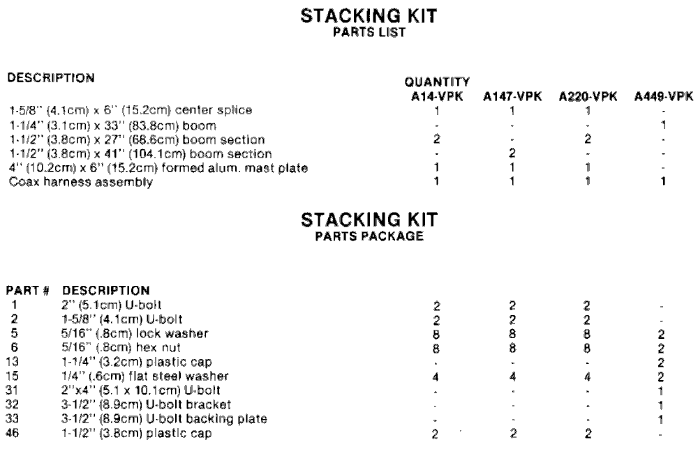
To assemble the A147-22, A147-VPK, A14-VPK and A220-VPK mounting booms, slide the 1 1/2" (3.8cm) sections into the 1-5/8" (4.10cm) center splice, as far as the single black line. The 4" x 6" (10.2 x 15.2cm) mounting plate and U-bolt clamp the sections together, Figure 6. The A443-VPK mounting boom uses a single U-bolt and bracket assembly in the center, Figure 2.
Mount the antennas on the ends of the support boom, using Chart 1, Dimension A, for the proper spacing, which is measured center-to-center on the antenna booms. For mechanical balance, it is best to keep the antenna booms below the support boom. The Reddi-Match rods should be on the same side of the antenna booms, and pointing up. Press the plastic caps into the boom ends.

Two arrays can be mounted in aquad configuration by using the appropriate coaxial harness between the dual arrays, Chart 1. In this case, the gain of the system will be nearly 6dB over that of a single antenna.
Rear mounted antennas, such as the A147-4, A220.7, or A440-6, may be stacked along the side of the tower, one above the other. The tower should have little influence upon tuning, since it is behind the reflector elements. Recommended phasing harnesses and center-to-center stacking distances are given in Chart 1. For this configuration, the horizontal beamwidth of the array will be the same as for a single antenna, provided that the antenna booms are in the same direction. However, the vertical beamwidth (above and below the horizon) will be considerably narrower than that of a single antenna.
A stacked array consisting of two or four antennas may be conveniently tuned at ground level by temporarily resting the array on wooden or insulated supports so that the antennas are pointed up into the sky, and the reflector elements are parallel toand a few feet above the ground. Conducting objects behind the reflectors have little influence on antenna tuning, but be sure that the sky and area around the array is free from obstacles, such as buildings, wires, trees, etc. All antennas in the array should have the Reddi-Match units pointed in the same direction, so that they will be phased
Before connecting the phasing harness cables, tune each antenna at your center frequency, using a 50 ohm feedline from your transmitter, and a reliable S.W.R. bridge or reflectometer. Follow the procedure given for tuning a single antenna.
After tuning the antennas, tighten all connections, connect the harness and neatly dress and tape the cables along the booms and frame members. Excess cable may be coiled up equally on each side.
The SWR for the completed array may now be checked at the central coaxial "T"-connector using your 50 ohm feedline and SWR indicator. The SWR value should be low. It will not change appreciably, if the antenna is mounted high and in the clear.
Before final installation on your tower mast, install the connector boot over the connector. Apply the silicone grease around the PL259 connectors.
ASSEMBLY INSTRUCTIONS
- BOOM ASSEMBLY, A147-11, A220-7, and A220-11:
- Slide the 7/8" (2.2cm) section(s) into the 1" (2.5cm) center section,
as far as the single black line. To align the boom sections, insert a 2" (5.1cm) bolt through one hole in each section,
and sight along the boom. Tighten the sections securely with the 1" (2.5cm) telescope clamp(s).
- ELEMENT ASSEMBLY:
- The elements for the A147-4, A147-11 and A220-11 (not including the dipole) are taped in one
bundle. They are progressively shorter to improve bandwidth. For the A147-4, A220-7 and A449-6, mount the reflector
(longest element) at the U-bolt end of the boom. The A-147-11 reflector may be mounted at either end of the boom.
For the A220-11, mount the reflector at the end of the 1" (2.5cm) boom section. Mount the dipole next, then each
progressively shorter director, up the front director (shortest element), Figure 1. All but the two end elements and dipole
are preassembled on the booms of the A449-6 and A449-11. Mount them in the proper order as outlined onto the
dipole and boom ends.
- MAST MOUNT:
- The A147-4, A220-7 and A449-6 use a single U-bolt and bracket assembly, Figure 2. The A449-11 and
A220-11 use a single U-bolt and bracket assembly, Figure 3. The A-147-11 uses a 4" x 6" (10.2 x 15.2 cm) plate
mounted between the number 5 and 6 elements, Figure 4. All of the antennas may be mounted for horizontal or
vertical polarization. For vertical polarization, mount them with the Reddi-Match rods pointing up. Keep the mast mount
bracket on the opposite side of the boom from the elements. This will help to minimize pattern distortion from
metallic masts.
- TUNING:
- The Reddi-Match is set at the factory for 50-ohm and center band operation. For best results, it should be individually tuned at your site, by using a good quality standing wave ratio bridge. It is not necessary to cut your feed line or prune it to a particular length; any length feed cable may be used with the beams. However, the cable should be as short as possible to reduce feed line losses. Your feed cable should be equipped with a standard PL-259 coaxial fitting, to connect to the Reddi Match, Figure 5. Tune the antenna at your center frequency, using a 50-ohm feed line from your transmitter, and a reliable S.W.R bridge or reflectometer. Connect the S.W.R. bridge to the antenna with a short length of RG-8/U or RG-58/U coaxial cable (preferably an electrical 1/2-wave length, so that the actual S.W.R. value at the antenna feed-point will be repeated at the bridge.) Slide the Reddi-Match tuning strap in either direction, to obtain the lowest S.W.R. reading. Move away from the antenna and check the reading. Repeat this procedure until the S.W.R. reading is at its lowest value. Disconnect the cable and bridge, and tighten the tuning strap securely. When the antenna is completely assembled and tuned, tighten and tape the feed line connection, and coat with a clearacrylic spray or equal. The connections may be internally weatherproofed with silicone grease, if desired. Run the coaxial feed line along the boom, away from the elements, and down the mast. Use electrical tape to hold it in position.
INSTALLATION SUGGESTIONS
Your Cushcraft VHF/UHF beam is designed and manufactured to give top performance and trouble free service. The antenna will perform as specified, if the instructions and suggestions are followed, and if care is used in assembly and installation.
- MASTING:
- The mast mount brackets on the A147-11, A220-11, and A449-11 will take up to a 1 1/2" O.D. mast. A 1 1/4"
O.D. television type tubing is satisfactory for any of the single beams. The A147-22 Power Pack may be mounted on a
mast of up to 2" O.D. The A147-4, A220-7, and A449-6 have extra-length booms for mast or tower side mounting, and
may be mounted on a support of up to 2" O.D.
- MOUNTING:
- When mounting the beams on the same mast with other VHF/UHF antennas, they should be mounted
at least 1/2 wave length (of the lower frequency) away from the other antennas. The beams may be mounted within 6
ft. of 6 meter or HF antennas. Generally, it is best to mount these beams above lower frequency antennas.
- ROTOR:
- A good quality television antenna rotor will easily handle any of these antennas.
LOCATION of the antenna is very important. Surrounding objects such as trees, power lines, other antennas, etc. will seriously reduce efficiency. To minimize the effects of surrounding objects, mount the antenna as high and in the clear as possible. If metal guy wires are used, they should be broken with strain insulators.
WARNING: THIS ANTENNA IS AN ELECTRICAL CONDUCTOR, CONTACT WITH POWER LINES CAN RESULT IN DEATH, OR SERIOUS INJURY. DO NOT INSTALL THIS ANTENNA WHERE THERE IS ANY POSSIBILITY OF CONTACT WITH OR HIGH VOLTAGE ARC-OVER FROM POWER CABLES OR SERVICE DROPS TO BUILDINGS. THE ANTENNA, SUPPORTING MAST AND/OR TOWER MUST NOT BE CLOSE TO ANY POWER LINES DURING INSTALLATION OR REMOVAL OR IN THE EVENT PART OF THE SYSTEM SHOULD ACCIDENTALLY FALL. CONSULT THE NATIONAL ELECTRICAL CODE FOR FURTHER DETAILS.
| Element Assembly Figure 1 
| Mast Mounting (A147-4, A220-7, A449-6) Figure 2 
| Mast Mounting (A220-11, A449-11, A449-VPK) Figure 3 
|
| Mast Mounting (147-11) Figure 4 
| Driven Element Assembly Figure 5 
| Stacking Mounting (A147-22, A147-VPK, A220-VPK) Figure 6 
|