I enjoy reading about the era, the times, the technology, and I enjoy talking to hams from the 20's and 30's as well. I would like to experience the radio adventures those hams had. I want to build my own 1920's equipment, put the 4 or 5 watts of raw blinding power on the air, get all excited to work a new state, and QSL with a vintage QSL card. To that end, I am building a 1927 ham transmitter using 1920's parts where possible. I've just made my first 3 QSO's with my transmitter, though I'm still trying to tame the buzz and chirp. I'm planning to participate in the AWA 1929 Bruce Kelly QSO party.
Here are photo's and discussion of my 1927 transmitter. This lil gal has 'character' and you won't forget her sound on 80 meter, its an echo from 1927.
73, Scott WA9WFA
 |
Click on the thumbnail to get a larger photo. I modeled my 1927 transmitter after a real 1927 transmitter that is owned by John Dilks K2TQN and featured in his QST Column OLD RADIO. It also resembles a 1920's AERO transmitter. Note the striking resemblence to the AERO and the authentic 1927 transmitter photo's below. |
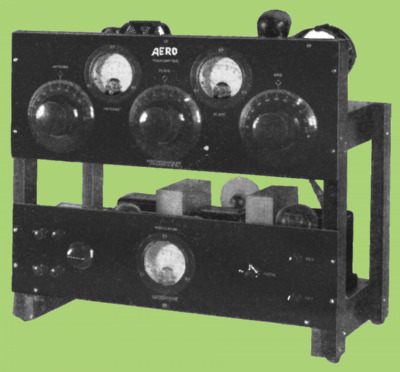 |
Click on the thumbnail to get a larger photo. Here's a photo of the 1920's AERO transmitter. Photo from John Dilks K2TQN website. |
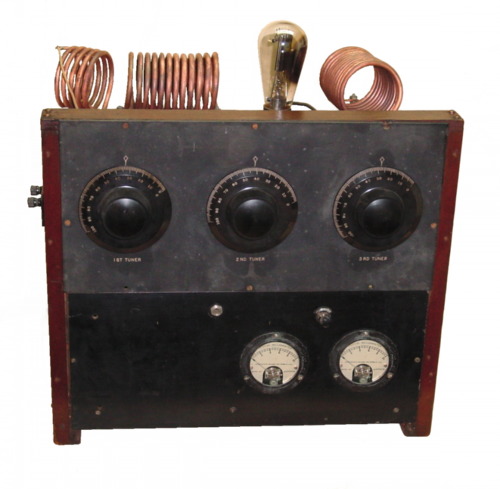 |
Click on the thumbnail to get a larger photo. Here's a photo of John Dilks authentic 1927 transmitter. Photo from John Dilks K2TQN website. |
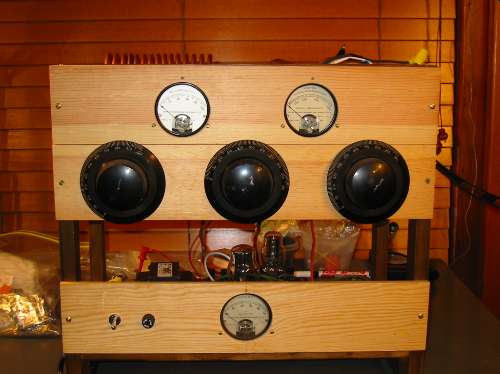 |
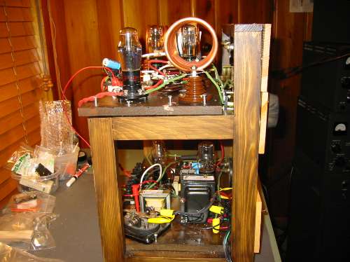
Click on the thumbnail to get a larger photo. Here is a photo of the front of my 1927 transmitter. The transmitter is on top shelf, the power supply is on the bottom shelf. The meters on top measure amplifier plate current (L) and antenna current (R). The meter on the bottom measured plate voltage. The knobs and meters are all period. The frame is pine. The backsides are stained dark. The front panels are yellow pine, natural. The look of the transmitter has a strong resemblance to the AERO transmitters of the era as well as the homebrew 1927 transmitter that I used for a model. |
 |
Click on the thumbnail to get a larger photo. The wood frame was given to me by my friend John Dilks. It duplicates a real 1927 transmitter that he owns. The transmitter is on the top, the power supply on the bottom. Both the transmitter and power supply are assembled on pine boards, just like they did in the 1920's. The transmitter is 95% constructed using 1920's parts. It took me nearly a year to acquire period parts to make the transmitter as authentic 1927 as possible. The power supply is modern though it uses an 80 rectifier tube. |
 |
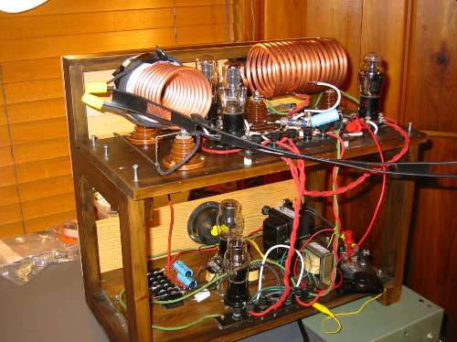
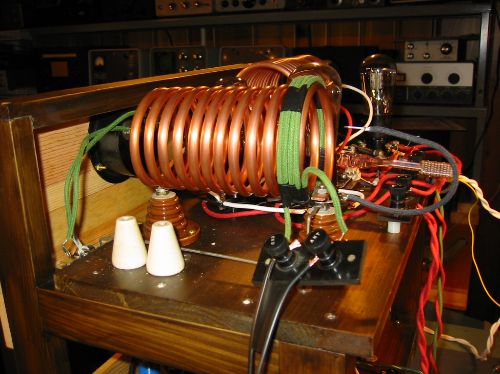
Click on the thumbnail to get a larger photo. Here is a side view of the transmitter frame. The power supply is pretty much modern. It uses a brand new Hammond high voltage transformer, Hammond filament transformer, Hammond chokes, new electrolytic capacitors and resistors. The power supply provides 300 vdc full wave rectified using an 80 tube. The AC cord is a modern three wire cord and it is fused and switched from the front panel. While fuses, three wire AC, safety, are not period 1927, the transmitter needs to be safe. That statement is kind of an oxymoron considering I have 150 vdc and 340 vdc exposed on the copper tube coils. |
 |
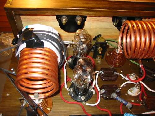
Click on the thumbnail to get a larger photo. Here is a photo of the oscillator section. The 27 oscillator tube is shown in the lower right hand corner. The oscillator coil consists of 15 turns of 1/4" copper tubing, handwound, and supported between two real brown beehive insulators. The variable capacitors are PILOT and from the 20's. The transmitter resistors and capacitors are period 1920's as well. Note that the modern electrolytic cap is being used for filtering while I try to get the chirp under control :) The wiring is modern reproduction 18 gauge solid with colored cloth covering. It looks like 1920's wire should except that it has modern PVC insulation under it, its rated for 600 volts, and its safer than 1920's wire. |
|
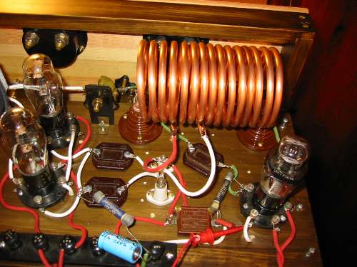
Click on the thumbnail to get a larger photo. Here is a photo of the amplifier section of the transmitter. On the left is the amplifier tank coil, 12 turns of 1/4" copper tubing. I'm still trying to work out the link coupling from the L to the antenna, so I'm experimenting with tight coupling as well as loose coupling to the primary. The pair of 27 tubes can be seen in the center. The amplifier fixed capacitors are 1920's Sangamo capacitors. The sockets are 20's as well. Note the cool brown Beehive insulators which are traditional on a 20's transmitter. In the lower photo I've settled on tight coupling, 4 turns at the B+ end of the coil. |
| Click on the thumbnail to get a larger photo. The results as of December 3, 2004 are pretty good. I'm able to get 2 watts output with 300 vdc at 50 ma on the plates. The signal actually sounds fairly good, minimal buzz, some chirp for character and nostalgia but not objectionable. I chose the Master Oscillator Power Amplifier (MOPA) scheme because I thought the oscillator would be better isolated from the effects that cause chirp. While I expect this transmitter to always have chirp, it does need to be tamed a bit. It will be a fine balance between power output and signal quality. | |
| Click on the thumbnail to get a larger photo. Here is the schematic diagram. |
This site was last updated 12/03/04