 Click on the thumbnail
photo to bring up a large picture.
What a
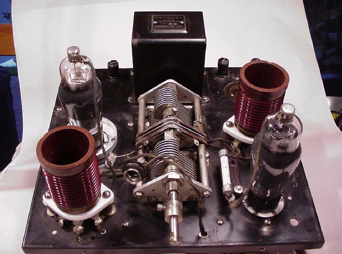
gorgeous chassis, even after 70 years! Here is a close
up the SW-3 chassis with the cabinet removed. The back
of the cabinet is
completely removed, then the chassis is detached from
the cabinet and slid out the rear of the
cabinet. The photo shows the chassis with the
tubes and coils installed. The front of the chassis is
towards the bottom facing you. The
RF amplifier coil and tube (6C6) are located on the
lower left. The detector coil and tube (6C6) are
located on the lower right. The dual ganged tuning
capacitor is in the center and the audio coupling
transformer is located along the center rear of
the chassis. The tuning capacitor is a dual capacitor
but a single assembly which suggests its a Model II. Click on the thumbnail
photo to bring up a large picture.
What a
gorgeous chassis, even after 70 years! Here is a close
up the SW-3 chassis with the cabinet removed. The back
of the cabinet is
completely removed, then the chassis is detached from
the cabinet and slid out the rear of the
cabinet. The photo shows the chassis with the
tubes and coils installed. The front of the chassis is
towards the bottom facing you. The
RF amplifier coil and tube (6C6) are located on the
lower left. The detector coil and tube (6C6) are
located on the lower right. The dual ganged tuning
capacitor is in the center and the audio coupling
transformer is located along the center rear of
the chassis. The tuning capacitor is a dual capacitor
but a single assembly which suggests its a Model II. |
 Click on the thumbnail
photo to bring up a large picture.
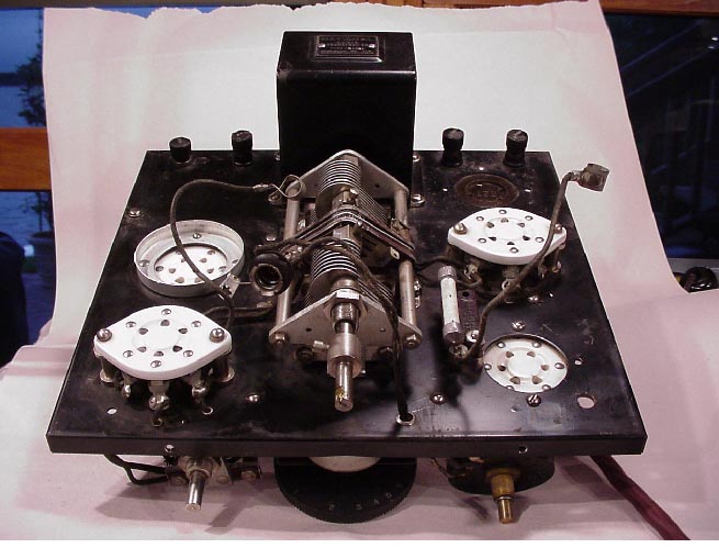
This photo
shows the chassis without the tubes or coils. The
white socket in the lower left is the rf amplifier
coil socket. The white
socket in the upper left is the rf amplifier tube
socket. The white socket on the lower right is the
detector tube socket. The white socket on the upper
right is the detector coil socket. In the upper right
corner is a brown tube socket for the audio
amplifier tube. Note that the coil sockets and the rf
amplifier and detector tube sockets are made of
porcelain, a high performance tube socket, so even in
the minimalist radio, National used top quality high
reliability components. I notice they
didn't use a porcelin socket for the audio amplifier
tube socket in the upper right corner. Along the
back of the chassis (photo top) is a series of screw
terminals. The pair on the upper right side is for the
head phones. The terminal unscrews
allowing the user to insert the headphone pin and then
tighten the screw. The pair on the upper left is the a Click on the thumbnail
photo to bring up a large picture.
This photo
shows the chassis without the tubes or coils. The
white socket in the lower left is the rf amplifier
coil socket. The white
socket in the upper left is the rf amplifier tube
socket. The white socket on the lower right is the
detector tube socket. The white socket on the upper
right is the detector coil socket. In the upper right
corner is a brown tube socket for the audio
amplifier tube. Note that the coil sockets and the rf
amplifier and detector tube sockets are made of
porcelain, a high performance tube socket, so even in
the minimalist radio, National used top quality high
reliability components. I notice they
didn't use a porcelin socket for the audio amplifier
tube socket in the upper right corner. Along the
back of the chassis (photo top) is a series of screw
terminals. The pair on the upper right side is for the
head phones. The terminal unscrews
allowing the user to insert the headphone pin and then
tighten the screw. The pair on the upper left is the a
Along the lower front edge of the chassis you can see the rf tune capacitor, horizontal volume control pot and knob, and the regeneration potentiometer. |
 Click on the thumbnail
photo to bring up a large picture.
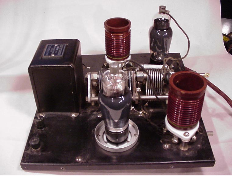
This photo
shows the left side of the chassis. This view shows
the antenna and ground terminals on the lower left
side. The assembly
around the rf amplifier tube is for a tube shield
which is not shown. Click on the thumbnail
photo to bring up a large picture.
This photo
shows the left side of the chassis. This view shows
the antenna and ground terminals on the lower left
side. The assembly
around the rf amplifier tube is for a tube shield
which is not shown. |
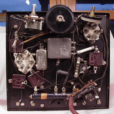
Click on the thumbnail photo to bring up a large picture. Here is a close up of the underside of the chassis. Not a lot of parts is it. The "front" is up, the "back" is down. Oops, you can see a couple of temporary tacked on troubleshooting fixes. Other than my tacked on resistor which fixes an open R7 resistor section, and the tacked on wire/resistor in the upper left which fixes a previous owner wiring modification, the SW-3 components are well secured to the chassis for stability. |