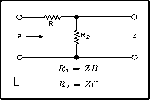
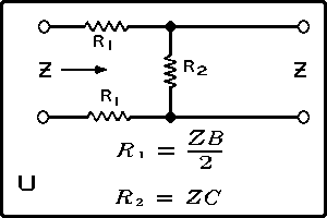
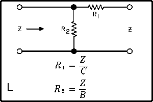
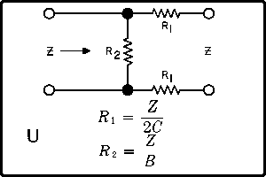
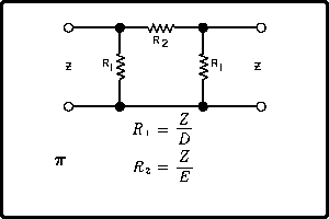
For data covering networks between unequal
impedances, see Minimum Loss Pads on page 10.
See also Decibel-Voltage Current
and Power Ratio Table on page 6.
See table on page 7 for values of A, B, C,
D, E used in the following attenuator network
formulas.
In case of L and U networks where only the
input or output can be matched, as required,
the matched side is
indicated by an arrow
pointing toward the pad. On all other networks,
input and both the output circuits are matched.
