|
To Bottom of Page |
Page 73 |
Return to Table of Contents |
HOME |
| EIA STANDARD RS-172 | MILITARY STANDARD MIL-R-11E |

|
| Color |
1st Digit A |
2nd Digit B |
Multiplier C |
Tolerance D |
Failure Rate* E |
|
Black Brown Red Orange Yellow Green Blue Violet Gray White Gold Silver No Color |
0 1 2 3 4 5 6 7 8 9 --- --- --- |
0 1 2 3 4 5 6 7 8 9 --- --- --- |
1 10 100 1,000 10,000 100,000 1,000,000 10,000,000 100,000,000 --- 0.1 0.01 --- |
--- ± 1% ± 2% ± 3% ± 4% --- --- --- --- --- ± 5% ± 10% ± 20% |
--- 1.0 0.1 0.01 0.001 --- --- --- --- solderable* --- --- --- |
| INSULATION CODING |
MILITARY (MIL):Same as EIA with the
addition of: Noninsulated resistors with ra- dial leads designated by a black background color or by a background the same color as the first significant figure of the resistance value. |
|
|
EIA: Insulated resistors with axial leads
are designated by a background of any color except black. The usual color is natural tan. Noninsulated resistors with axial leads are designated by a black background color. |

|
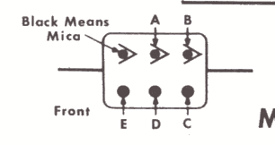
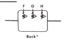
Mica Capacitor Color Code MILITARY STANDARD MIL-C-5C |

|
| Color | Digits of Capacitance (uuf) |
Multi- plier C |
Tolerance % D |
Characteristic. See table below. |
Working Volts DC F |
Operating Temperature G |
Vibration Grade(cps) H |
|||||||||||||||||||||||||||||||||||||||||||||||||||||||||||||||||||||||||||||||||||||||||||||||||||||||||||||
| A | B | |||||||||||||||||||||||||||||||||||||||||||||||||||||||||||||||||||||||||||||||||||||||||||||||||||||||||||||||||||
|
||||||||||||||||||||||||||||||||||||||||||||||||||||||||||||||||||||||||||||||||||||||||||||||||||||||||||||||||||||
|
DESCRIPTION OF CHARACTERISTIC |
VOLTAGE RATING
(Indicated by dimensions rather than color coding) |
||||||||||||||||||||||||||||||||||||||||||||||||||||||
|
|
||||||||||||||||||||||||||||||||||||||||||||||||||||||
|
Return to top |
PAGE 73 |
Return to Table of Contents |
HOME |