Solid State Directly Coupled Driver
for Class B Modulator Tubes
Review of Class B tube operation:
The standard definition of class B operation is that the conduction
angle is 180 degrees or that the plate of the tube in question conducts
for 1/2 the input cycle. Two tubes in a push pull configuration are needed
for audio, so that the other tube can complete the output for the other
half of the input cycle while the first tube is cutoff.
When tubes are to be grid driven, then the positive going half of
the input cycle turns on the plate conduction. Driving the grid more positive,
causes the plate current to increase and the plate voltage to decrease,
until the plate voltage has been reduced to zero. This point is known as
saturation (a more positive driven grid, will not cause an increase in
plate current, because the plate voltage has been reduced to zero).
Class B circuits typically have a lower plate load resistance than
Class A. This allows a much larger swing in plate current before the plate
voltage hits zero (saturation). Which of course means it can accept more
drive, reaching saturation at a higher plate current which yeilds more
output power.
 Problems:
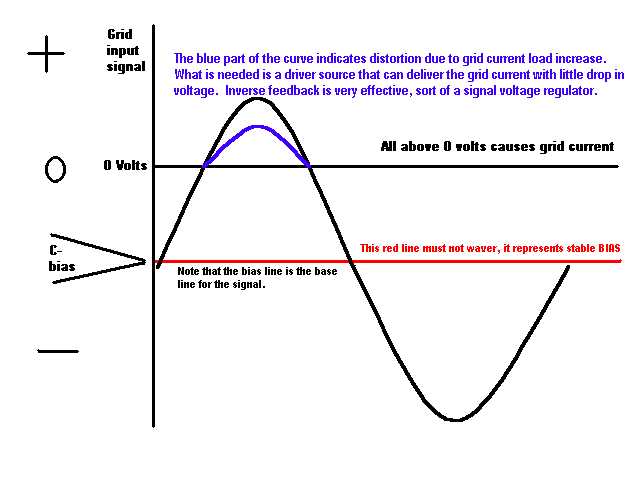
The grid is often driven far above the zero voltage point (with
respect to the grounded cathode) so that the tube draws grid current. This
causes an extra load on the driving stage, but only while the grid draws
current. This sudden increase of load on the driving stage will cause distortion
of the applied signal voltage. That is to say, that the voltage will not
go as high as it would have, had the load not increased.
The other problem is what to do with the current that is drawn from
the grid. If the circuit uses zero bias tubes and the plate supply for
the tubes is kept low enough to use the zero bias technique, then we can
simply send the grid current directly to ground. Generally this is done
by grounding the center tap of the driver transformer. But if the tube
requires a negative bias voltage to hold the plate current back to near
zero, then the grid current must be disposed of without letting it cause
the bias voltage to go more negative. Should this occur, then the bias
would not be right for Class B, instead it would be more like Class C,
(very distorted for audio).
Solutions:
Driving Class B control grids poses two problems.
-
Maintaining a constant bias voltage whether the input signal is above
or below the grid current condition.
This is done using a shunt (parallel) regulator from the bias point
to ground.
The bias power supply does not have to supply current to anything,
it is just there to provide a static voltage to the grids of the tubes,
but the regulator must be there to get rid of the current that is produced
by the grids input signal.
-
Keeping the input signal undistorted whether the input signal is above
or below the grid current condition.
This is generally done by special inverse feed back circuits. This
will automatically adjust the amplification of the driving stage under
varying load conditions. Keeping the wave shape of the input signal undistorted
even though the load may change while the full 360 degrees of the input
wave has not been completed. You might say it is signal regulation.
Another way to help this condition is to have a driving stage that
is capable of much more driving current than is ever drawn by the grids
of the modulator tubes. In this way, the grid current is only a small percentage
of the capability of the driving stage. Therefore the distortion produced
by grid current load change is also very small.
Summary:
There is no perfect solution, but the distortion caused by the above
mentioned problems can be reduced to levels undetectable or certainly exceptable.
The following diagram shows my solutions in more detail.