Hallicrafters SX-28 and SX-28A For Sale
These two receivers were SOLD at the "Sussex County Hamfest" on 7/13/2008.
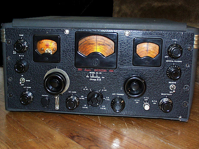
SX-28A
Click on image for large JPEG
New Fixes on SX-28A 4/17/1998!
Contents
What's the difference between the SX-28 and SX-28A?
I have read a few accounts of the differences between the SX-28 and the later SX-28A.
I own both. Here is what I have found. In an advertisement for the SX-28A in the 1946 edition of the Radio Amateurs
Handbook I have extracted the following text out of context. "The SX-28A is a further refinement of the famous
Model SX-28 that achieved such popularity with amateur and professional operators prior to Pearl Harbor.".......
"The traditional sensitivity and selectivity of the Model SX-28 have been further improved in this new Super
Sky-Rider [SX-28A] by use of "micro-set" permeability-tuned inductances in the r.f. section. The inductances,
trimmer capacitors, and associated components for each r.f. stage are mounted on small individual sub-chassis [phenolic
boards] and may be removed as a unit for easy servicing."
I have taken photos of the r.f. sections from the pre-WWII SX-28 (1940) and late WWII SX-28A as shown below. The
inductors in the SX-28 are mounted directly to the main chassis and are adjusted using the protruding screws. Whereas,
in the SX-28A, the inductors and capacitors for each section are mounted on boards to form modular units. The inductors
are tuned by directly accessing the notched tuning slugs. I have the manuals to both the SX-28 and SX-28A. After
examining the schematics carefuly, I have detected no differences in circuitry nor tube types. Both panels are
marked as an SX-28, however one other notable difference is that the cover over the tuning capacitors and RF tubes
on the SX-28A is fastened by snap-on fasteners holding the entire cover, whereas on the SX-28, a small cover over
the tubes is removable with thumb screws.
Panadaptor: A companion S-35 Panoramic Adaptor could be ordered with the
receiver. A photo and additional information can be seen in Chuck Dachis book on Hallicrafters receivers.
This just in:
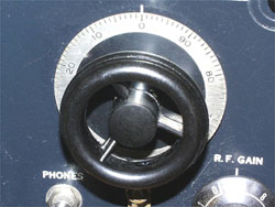
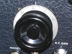
The most obvious way to tell an SX-28 from an SX-28A without looking inside is simply
by noticing that the older SX-28 model had true "steering wheel" type tuning knobs with no material between
the spoke. This was pointed out to me by Warren D. Anderson in an e-mail I received from him on 11/5/1998.
 |
On the '28, the "steering wheel" style
tuning knobs have true spokes
between which there is no other
material. |
 |
On the '28A, the tuning knobs do not
have true spokes because there is
knob material (bakelite?)between
them. |
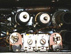 |
RF inductor section under the chassis
of the SX-28. Tuning is accessed through
brass screws. |
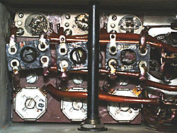 |
RF inductor module or subchassis under
the chassis of the SX-28A. Note tunable
slugs in bakelite coil forms. |
 |
SX-28 RF Section containing tuning
capacitors and tubes shows removable
thumbscrew plate. |
 |
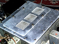
In the SX-28A RF Section, the entire
cover is fastened with 4 snapfasteners. |
SX-28 or SX-28A SPECS
Bands
| Band 1 |
550 to 1,600 KHZ |
| Band 2 |
1.6 to 3.0 MHZ |
| Band 3 |
3.0 to 5.8 MHZ |
| Band 4 |
5.8 to 11.0 MHZ |
| Band 5 |
11.0 to 21.0 MHZ |
| Band 6 |
21.0 to 43.0 MHZ |
Tubes
| 1-6AB7 |
1st RF Amplifier |
| 1-6SK7 |
2nd RF Amplifier |
| 1-6SA7 |
Mixer |
| 1-6SA7 |
HF Oscillator |
| 1-6L7 |
1st IF Amplifier Noise Limiter |
| 1-6SK7 |
2nd IF Amplifer |
| 1-6B8 |
2nd Detector and S meter tube |
| 1-6B8 |
AVC Amplifier |
| 1-6AB7 |
Noise Amplifier |
| 1-6H6 |
Noise Rectifier |
| 1-6J5 |
Beat Oscillator (BFO) |
| 1-6SC7 |
1st Audio Amplifier |
| 2-6V6GT |
Push-Pull Audio Output Amp |
| 1-5Z3 |
Rectifier |
Electrical
| Power Consumption: |
@ 117V-60HZ-138W |
| Power Output: |
8W undistorted |
| Sensitivity: |
(for 500 mw output) varies
between the limits of 6 to 20
microvolts over the entire
frequency range of the receiver. |
| |
|
| Selectivity: |
IF broad (hi-fi) |
| |
IF Sharp |
|
| 2 x |
1000 X |
| 12 KHZ |
36 KHZ |
| 4.1 KHZ |
22 KHZ |
|
| Frequency response AF (audio filter out-broad IF-tone control high) |
70HZ to 3KHZ +/- 2db |
| Speaker Output Impedance: |
5000 and 500 ohms (modern low-Z speaker can be connected to the headphone jack on the
front panel) |
| IF Frequency: |
455 KHZ |
| Weight: |
75 lbs. |
Restoration Logs
SX-28A Condition when received
Physcial:
Receiver chassis and components were all in shiny clean mint condition. Case is dirty
and badly dented in several places. Front panel in excellent condition with some chipping around screws. Antenna
terminal post pair was replaced with modern plastic type - not original. Almost all tubular capacitors had been
replaced with mylars.
Functional:
Reception works well on all bands and frequency calibration is fairly close. Tone quality
is excellent. BFO did not work, no signal with selectivity switch in crystal positions. S meter frozen in high
reading position. Bandspread band pointer string is broken. Everything else seems to work OK.
SX-28A Restoration Log
- Ordered and received reproductions of manuals for both the SX-28 and SX-28A from W7FG Vintage Manuals.
- I started by simply removing and replacing the BFO tube to make it work - just a bit
of dirt, I guess.
- Removed s meter, needle was physically frozen. Disassembled s meter and found needle
pivot out of pivot screw. I reset it with no problem. Upon replacing s meter functioned, but no sensitivity. I
measured the 27K 2W resistor in the S-meter tube anode circuit, (R30). It measured around 50K. Went to Radio Shack
and all I could find were 2, 100K 1/2 watt resistors which I slapped in parallel with the bad resistor to give
me a value of about 24K. This made the S-meter work properly, but the resistors heat up too much and the meter
often has to be re-adjusted. Bought 27K 10W resistor at Lashen Electronics in Denville, NJ, but haven't used it yet.
- Eyeballed crystal filter area and compared it with the other SX-28 and found a wire
broken. On resoldering the wire there is now a signal when when the selectivity switch is in the crystal positions,
but the filter hardly works very well. No noticable difference when crystal phasing is adjusted.
- Ordered dial cord for bandswitch pointer, still waiting.
- Ordered gray wrinkle paint for cabinet, still waiting.
- Asked one autobody shop for estimate on smoothing out the cabinet. The guy said he
was really swamped and it would probably cost me a couple hundred. Then at a hamfest, I asked a collector/restorer
and he recommended that I get the cabinet dipped to strip the paint and buy some Bondo & hardiner and puddy
the thing myself. I will get the cabinet paint stripped and ask a couple more autobody shops before trying this
myself.
- 4/6/98 Received gray wrinkle spray paint for cabinets and new dial drive cable for
band switch pointers from Antique Electronic Supply part number S-M75A-25, 0.028" (Standard Thin).
- 4/6/98 Replaced S-meter tube anode resistor (R30) with 2.7K 10W.
- 4/6/98 Installed new dial cord making bandspread band pointer operate with bandswitch.
Only problem with receiver at this point seems to be the selectivity control and crystal filter don't seem to be
adjustable. S-meter is somewhat stingy. SX-28 S-meter (other receiver) more sensitive once I got it working on
4/11/98. Need to check the circuit out. Maybe a weak 6B8 tube (V7). Put that on my list.
- 4/11/98 Got Crystal filter to operate. The outside crystal phasing capacitor terminal
was toucing the metal sheild around it. I simply bent the pin from the shield. So, that combined with the previously
reconnected wire underneath the chassis put the crystal filter into operation. The "Broad", "Medium"
and "Sharp" don't seem to behave in that order, though.
- Stripped old paint from case, got dents knocked out and filled by autobody man. Got
case repainted.
- Bought good old fashioned rack screws and washers. Waldom 10-32 X 3/4" Oval Head
machine screws, Steel Nickel plated #KF-510. Waldom #8 screw size Steel Cup Washers Nickel Plated #KCW-8. --- at
Lashen Electronics.
BANDSWITCH POINTER THREADING
(Two versions)
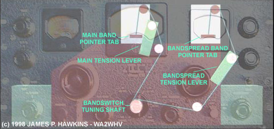
Someone sent me some E-mail asking me how to thread the dial cord for
an SX-28. The manuals for the SX-28 and SX-28A do not contain instructions or a picture, so I had to figure it
out for myself. After doing so, I created the figure below using 3D Studio MAX 2 and Photoshop. For those interested
I will explain a bit of that process. I suppose there are are other, cheaper tools, but it was easier for me to
actually construct a rough 3D model of the panel, chassis and other parts with the panel material set to transparent.
The panel picture was obtained by taking a picture of it with my digital camera, loading it into Photoshop, adjusting
the brightness to maximum and the contrast to almost minimum so that a faded image would be created. After placing
the parts, in 3D Studio MAX 2 I simply created a line following the path and lofted a circle onto the line. If
you don't understand what that means, it doesn't matter for this discussion. Since there weren't any instructions
for this, I had no idea what the parts were called, so I made up my own names for the parts. The "bandspread"
dial is really a hamband dial which is calibrated only for 10, 20, 40 and 80 meters. I converted the picture to
grayscale to make sure that the parts contrasted properly for the "color challenged."
First Version
- One string is going to be used for both switches so start by cutting a piece of dial
drive cable about 3 feet long and dip the ends in or paint the ends with nail polish or some other lacquer. Set
aside to dry. The nail polish will harden the ends making it possible to thread the cable through the small holes
in the pointer tabs.
- First, remove and clean any old remaining dial cord from each pointer tab.
- Place the bandswitch in the .55-1.6 MC position (for least tension)
- Loosen both the main and bandspread tension levers so that they move with some friction
(not flopping around) and position them to the upright position (for least tension).
- Now, take the dial drive cable and cut one of the ends in within the nail polished
area and thread it through the hole in the main band pointer tab then tie it. The pointer tabs are attached to
front of the spring loaded assembly which can be pulled up and down to slide the band pointers.
- Wrap the cord around the top pulley, the pulley on the end of the main bandspread
tension lever and then the third pulley attached to the chassis. It helps to have a pair of long slim needle-nose
pliers to grab the cable while feeding it through tight spaces.
- Continue down to the bandswitch and wrap the cord around the screw in the side of
the bandswitch shaft.
- Do NOT go directly to the next pulley, but wrap once clockwise around the bandswitch
shaft, feeding it UNDER the loop to prevent slippage, then continue to the pulley just below the bandspread tuning
shaft.
- Continue up to the pulley fastened to the bandspread tension lever and then to the
topmost pulley on the bandspread band pointer assembly.
- Continue around that pulley down to the tab on the spring-loaded bandspread pointer,
cutting this end within the nail polished area. Feed it through the hole in the tab and tie it slightly tight.
- Once the entire cord is in place, with the bandswitch in the .55 - 1.6 MC position
position the main tension lever so that the pointers pount to the bottom most band calibration (standard broadcast).
- Now move the bandswitch to the 3.0 - 5.8 MC position for adjustment of the bandspread
pointer.
- Now adjust the bandspread tension lever, tightening the cord till it points to the
bottom most band calibration line. I will help if you lift the spring-loaded pointer assembly with your finger.
- That's it! Now, hopefully, when you turn the bandswitch it will pull the string for
both pointers, moving them to the appropriate band. Note that when the bandswitch is in either the .55 - 1.6 MC
and 1.6 - 3.0 MC positions, the bandspread pointer is pointing below the lowest band on the bandspread dial since
there is no corresponding band for those positions. If the pointers are not correct try adjusting the tension levers.
If that doesn't work, you may have to untie an end, tightening it up and retying it. Unfortunately, on my SX-28,
the bandswitch had no mechanical limits to prevent continuous rotation. The switch should not be capable of moving
directly from the .55-1.6 MC position to the 21-42 MC position. If it is and you do that it will either break the
string, make it slip or fall out of the pulleys. My SX-28A has such limits, but I haven't yet figured out where
it's implemented. If anyone has any ideas, please drop me a note.
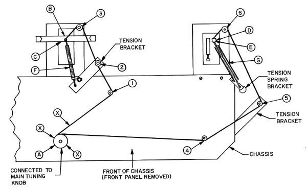
Second Version
Ken Kinderman - WB9OZR saw this page and sent me a threading diagram and instructions
that he obtained. Neither one of my receivers match this diagram identically so I will keep my diagram up, although
I do need to add the spring on the bandspread side. I have been told that these receivers vary somewhat even within
the same model. Below are the text copied directly from the instructions with the diagram.
- Make sure both metal indicator arrows are in the down position and there is no tension
on the springs (F) and (G).
- Set the receiver on end with bottom of chassis facing the operator.
- Set the band switch to position 1.6-3.0 MC. (Machine screw on band switch shaft bushing
is now facing operator.)
- Cut the dial cord at leas 26 inches long.
- Make a slip knot 10 inches from one end of cord; place over machine screw (A), and
draw tight.
- Set band switch to position .55-1.6 MC.
- Wind short end of cord once around bushing (X), then position cord over pulley (1),
under pulley (2), and over pulley (3).
- Open slot (B) with pliers; run cord through brass blocking washer, tie a double knot,
and insert through slot (C). (Do not allow any slack in cord.)
- Close (B) with pliers.
- Position the longer length of cord under pulley (4) and over pulley (5) and pulley
(6) respectively.
- Insert and pull cord through brass sleeve (D) and blocking washer, and tie cord to
end loop (E) of tension spring (G), allowing only a slight tension on spring. Make sure there is no slack in this
length of cord.
- Turn band switch to each of the six positions, noting the position of the metal indicator
arrows.
- Tension and position of the knots with respect to the brass blocking washers are critical,
making careful stringing of the cord necessary. Adjust the tension brackets if necessary. (Cord may break if not
correct.)
SX-28 Condition when received
Physical:
Receiver in good physical condition with no damage, but very dirty. Both main tuning
and bandspread pointer cords missing, but threading will not be difficult. Unlike the SX-28A most caps and resistors
are the original. Cabinet is badly dented and is not an SX-28 cabinet. The power cord was completely missing. Some
controls were loose.
Functional:
Receiver works well on all bands and calibrations is close. Crystal filter works better
than on the SX-28A, but not very well. S meter somewhat. Front panel in mint condition! Selectivity doesn't seem
to work as expected.
SX-28 Restoration Log
- Found a spare PC power cord and cut the female end off. Standing the unit on its side
with power transformer side down, I fed it through the hole in back of the chassis, next to the power transformer
and stripped it, connecting the green wire (for the ground prong) to the nearby ground lug next to the octal socket
on the back of the chassis. The other two wires were connected to pin 5 of the tranformer and to the end lug of
the fuseholder.
- Not knowing what would happen upon applying power, I tipped the unit back to its normal
position. One electrolytic capacitor looked a bit crushed between the clamps holding it and having experienced
exploding electrolytic capacitors before, I wanted to protect myself before applying power. It's wise to sit the
chassis on a non flammable surface that you don't care about. Fortunately the receiver worked with no sparks or
smoke.
- Ordered dial cord for band switch pointers.
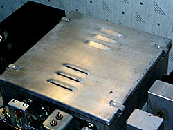
- Cleaned RF section covers to look mint using Clorox brand "Soft Scrub" cleanser
using a toothbrush (see photo above).
- Cleaned the dirty tubes.
- Replaced S-meter bulb. Noticed 1/2" Grommet
around S-meter bulb dried up, needs replacement.
- 4/11/98 (R30) S-meter resistor way out of range. Replaced with 27K, 10W. S-meter now
operates fine. It seems to be much more sensitive than the one on the SX-28A. Found meter zero adjust pot (R29)
intermittent. Will need to replace that.
- 4/11/98 Found nothing wrong with selectivity control, except that the knob was on
wrong leading me to believe it wasn't working properly. Repositioned knob. Selectivity positions all seem to be
working perfectly!
- 4/11/98 Noticed some arcing inside one of the 6V6GT audio output tubes. Put that on
my list! Works OK for now.
- 4/11/98 Noted that most of the paper tubular caps are .01, .02 and .05 uF. Will probably
pick up a half a dozen of each all rated at 600V. More on the list!
- 4/11/98 At the suggestion of Hank Arney - KN6DI, I got some 3M (green) Stripping Pad
Cat. No. 7413 at the local hardware store and started to rub off the chassis dirt using no liquids. Works like
a champ! For very narrow spaces I pushed it with the end of screwdriver. I blew the loose dirt out with GC Electronics
"Airjet". There are other brands you can get at electronics stores. It's probably a good idea to wear
safety glasses and hold your breath while the dirt flies! (you wonder what kind of organisms are in it!)
SX-28 Restoration Tips From Contributors
A. B. Bonds
on Original Capacitors and Resistors
This seems to be a fairly common activity these days, but then there is a lot to restore.
Observations:
The unit in question is an SX-28 of fairly early vintage, has uninsulated power resistors. Cosmetically clean,
functioned only weakly. I noted that the power transformer had been replaced, as well as several wax caps. My guess
is that leakage killed the transformer.
Every wax cap in this unit tested suspicious. Even the blue kinda plastic Aerovox replacements were not reading
well. I use an old Heath magic eye cap checker, which does HV leakage tests. Most caps were a little leaky, some
terribly so. All of them would not read strongly, i.e., even at the best bridge balance the eye did not open very
far, if at all. Replacement caps checked fine. Many of the waxies were melted to the point that the innards were
loose in the tube.
Bottom line: Replace ALL of the wax caps, even if they look OK. They will fry sooner or later. See my post on getting to the RF deck. My primary amendment to that
is that three of the four modules must be removed completely for reasonable access, the total job takes 8-10 hours.
About half of the resistors were not in spec, given the rated tolerances. Most read too high, a few read too low
(by a factor often in some cases). About a third (of the total) were sufficiently far off to justify replacement,
a non-trivial pursuit.
General rules: Any resistor used for screen dropping (with a bypass cap) will be bad, due to excessive current
through the bad bypass cap. Any 1 meg resistor will read at least 1.5 megs. The plate resistor for the S-meter
amplifier will be way off. It is 27K, rated at 2 w. Mine read 73 k. The load on this resistor varies with rf strength,
but it can be as high as 3.5 w. Miraculously, none of the other power resistors were bad.
Bottom line: Check all resistors. In nearly all cases, you will not have to remove an end to do so.
General observation: Halli construction of the era was very robust. Leads are very tightly wrapped, and often crowded
on a lug. The chassis is deep and crowded, so there is a tendency to blow off a replacement because it looks impossible.
It is not impossible, and if you don't do it, that component will be sure to fail next. The situation reminds me
of the OB-GYN doctor who retired and took a course in auto mechanics. For his final project, he showed the instructor
a car in which he had done and entire engine rebuild. He was especially proud of the fact that he had done the
whole job
through the tailpipe....
73, and stick with it A. B. Bonds
A. B. Bonds on access of Caps
in RF Deck
There are 11 wax capacitors in the RF deck of a Hallicrafters SX-28. While it is possible
to replace a few of them with hemostats and a long thin soldering iron, some are so buried that they are not even
visible. There follows a description of how to open up this deck. It is not for the faint of heart. I am limiting
the description to access to the RF amplifiers, since they are the most difficult to get to otherwise. The theme
may be continued on to the oscillator etc. at your own pleasure.
- Remove the top of the RF/variable cap box and pull the four tubes.
- Tag and then desolder the wires connected to the last gang of both the main tuning
cap (two wires, one terminal) and the bandspread cap (3 wires, two terminals). I found the solder in this BA to
be _very_ high melting point, so you will need a hot iron.
- Turn the receiver over and rest it on its top with the rear apron facing you. All
descriptions of position will be with respect to this orientation.
- Go to your chiropracter for an adjustment.
- Use a 1/4" nutdriver to remove all of the screws on the upper edges of the RF
side shields (these screws hold the internal shields in place).
- Remove the two screws holding the back of the bandswitch to the rear panel.
- Turn the bandswitch to band # 2 (this is for access in the next step). Remove the
bandswitch knob. If the shaft has any burrs from the knob setscrews, use a fine file to smooth them down.
- Loosen the setscrews on the dial indicator drum (this is the brass cylinder that is
on the bandswitch shaft, located in the gearbox).
- Gently pull the bandswitch shaft all the way out. DO NOT lose the little tension spring
(looks like a bent washer) that is between the dial indicator drum and the front panel of the gearbox. Let the
indicator drum hang on its string.
- Loosen the setscrews on the antenna tuning shaft (at the coupler to the cap) and pull
the plastic tuning shaft all the way out.
- Find a GOOD Philips screwdriver, not a Chinese knock-off. Torn-up Philips screws are
impossible to remove, and the ones you have to hit next are in impossible places.
- Remove the four Philips screws that attach each side-shield to the chassis. They are
directly below the upper screws that you removed in step 5. This is easy on the right side. To remove the ones
on the left side, you must unclip the filter cap attached to that shield and unscrew (with a 3/8" nutdriver)
the attachments of the shielded pair that are grounded through the two inner mounting lugs of the power transformer.
By lifting the shielded pair (which is covered by some kind of brownish tubing) you can (barely) get to the Philips
screw heads. Also, remove the grounding lug for the filament circuit from the left shield.
- Desolder the wire going through the right shield to the rightmost coil in the rearmost
compartment.
- Tag and desolder the pair of wires that go to a switch wafer and run through the top
middle of the divider ("front") for the rearmost compartment.
- Unscrew the nuts holding the antenna input posts, thereby freeing the antenna leads
internally.
- Remove the screw and nut holding the braid connection that runs to the rear chassis
wall.
- Remove the Philips screws holding the dividers down. There are four for each divider.
A long grabber (hemostat) is essential to get these suckers out.
- Gently pry the sides of the RF compartment apart. Then, pull the rearmost divider
toward the rear to unhook it from underneath the baseplate in the next forward compartment.
- At this point the rearmost divider can be swiveled up to the left. There are some
more wires holding it in on the left side, but they do not have to be removed to get reasonable access to the tube
socket. This also affords good access to the next compartment.
- Replace all the caps and most of the Rs while you're there. I found that all three
caps in the rear compartment were marginally leaky (caused the eye on my Heath cap checker to close about halfway)
at 150 volts. Note that one of the caps is under a coil and can't even be seen from above. I also found about half
of the Rs to be out of spec (e.g., 135k for 100k).
- Reassemble, then go find a cold 807.
This whole process takes about 4-5 hours if done carefully.
Good luck! A. B. Bonds
A beautiful book called "Radios by Hallicrafterstm" by Chuck Dachis can be purchased. It contains hundreds
of high quality color and B&W photos plus a history of the Hallicrafters company. The book can be ordered throug
Antique Radio Classified.
Other Related Sites
Vacuum Tube Links