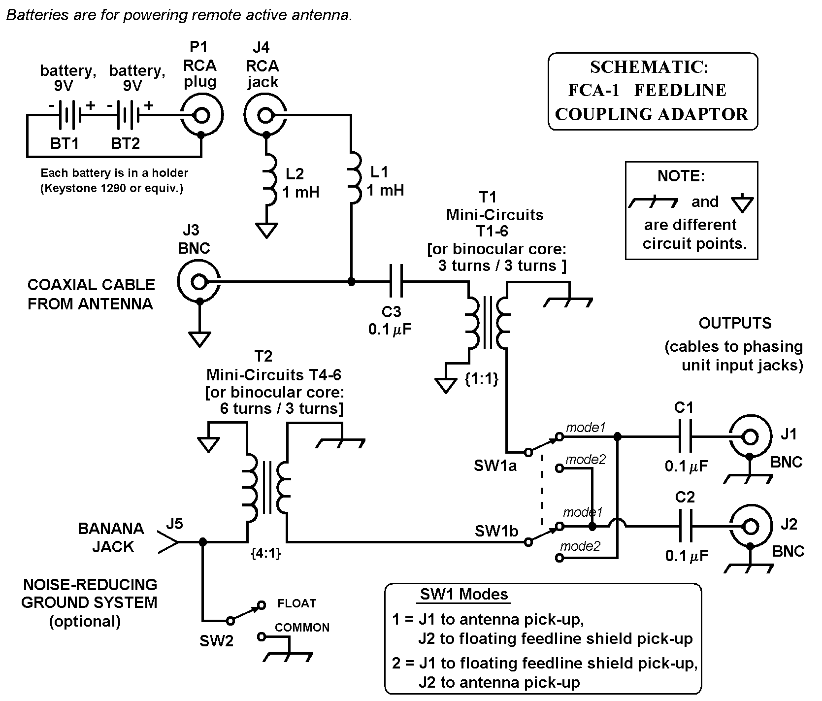
FCA-1 Feedline Coupling Adaptor
(Getting Two Antennas out of One)
Mark Connelly, WA1ION - 22 FEB 2002
The accessory described in this article allows the coaxial feedline going to a specific antenna to be used as a "second antenna". The trick to this is connecting the coaxial cable through a Mini-Circuits T1- 6 RF transformer (1:1 ratio) to separate the cable shield from receiver ground. The signal coming down the cable center conductor couples through that transformer (labelled T1 on the accompanying schematic) to supply the normal antenna output. A second transformer, T2, a Mini-Circuits T4-6 (a 4:1 ratio model) has its high- impedance primary connected to the coaxial cable shield and to a local ground (low-noise or the common receiver ground via switch SW2). The floating cable shield acts like a second antenna in this configuration. The low-impedance winding of T2 is routed to the output jacks via switch SW1.
If the antenna at the far end of the cable is an active whip or amplified broadband loop, DC power from a battery or other ground-isolated voltage source can be connected via J4. On the far end of the cable the DC would be choke-coupled to the amplifier. For passive antennas (such as a transformer-coupled Kaz, Pennant, Flag, or Beverage), the J4 DC input would not be used.
Inductors L1 and L2 should be rated for twice the anticipated DC-load current. Assembly of the FCA-1 is easiest if a plastic box is used rather than a metal one. Layout is not critical. Note that the cable shield "ground" at J3 (represented by a triangle) is different from receiver chassis ground at the J1 and J2 output jacks.
A major benefit of "floating" the coaxial cable shield is that if it picks up more noise or interference than the far-end antenna, it can be phased against the antenna signal to permit a significant reduction of electrical noise or interfering stations. The J1 and J2 outputs of the FCA-1 would be connected to the inputs of the chosen phasing unit (Quantum Phaser, MFJ-1026, or whatever). I have had good success with this system at several sites here in eastern Massachusetts.
FCA-1 Schematic

Click here for: PDF version of FCA-1 article
Click here for: RF Circuit Building Blocks Page