
"Old Stuff" collection
(click on any picture to enlarge)
| Tube/socket 204A; KRNT-AM | Farraday coil; KRNT-AM |
| 1934 Amplifier Metering Panel; KRNT-AM |
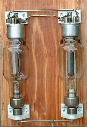
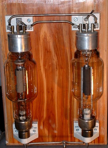
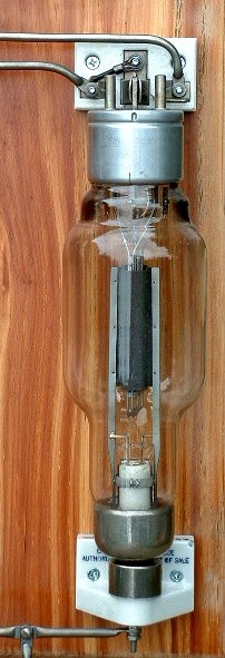
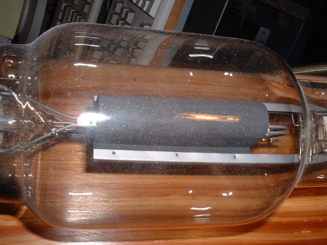
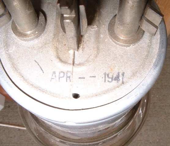
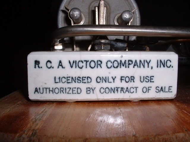
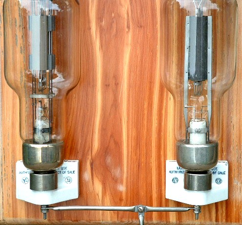
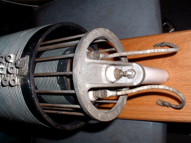
This 204A tube assembly was removed from the 1KW AM transmitter at KRNT radio in Des Moines, IA. Vintage of the exciter was likely early 1930's. The 204A can be used for an RF Amplifier or a Modulator. It is unknown at this time what the use was although my recollection is that there were four of these tubes (two assemblies) mounted on the wall of the transmitter.
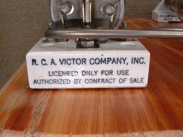
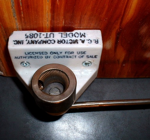
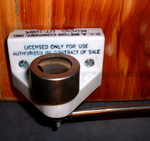
This tube is quite unique in the socket system that was used ... two non-attached ceramic bases mounted on a vertical surface.
Dimensions of the tube body is 12" long and 4" diameter.
Note that the pins on the upper end of the tube are not keyed, hence this end of the tube may be inserted into the upper socket in either of two orientations.
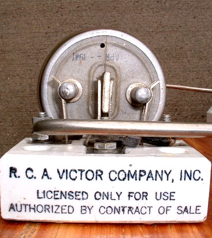
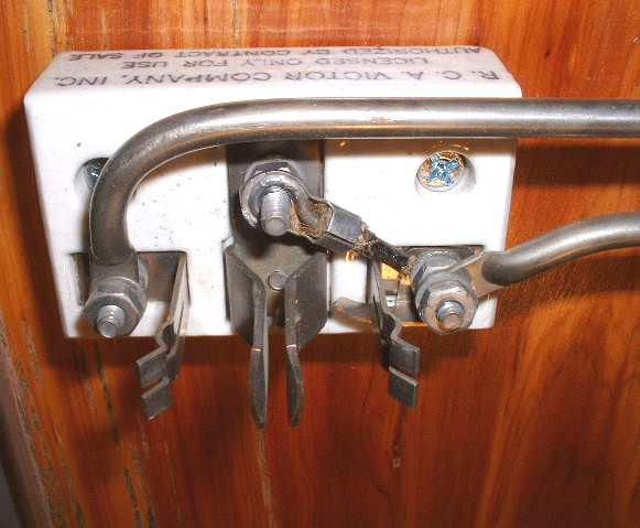
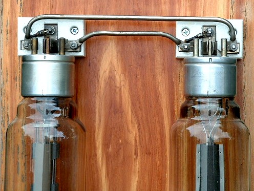
Note that the bottom socket is a spring arrangement allowing positive contact with the tube.
This is one (of two) meter panels removed from the
"home-built" amplifier at KRNT radio in Des Moines, IA. The 2-bay amplifier was
supposedly built on-site in 1934.
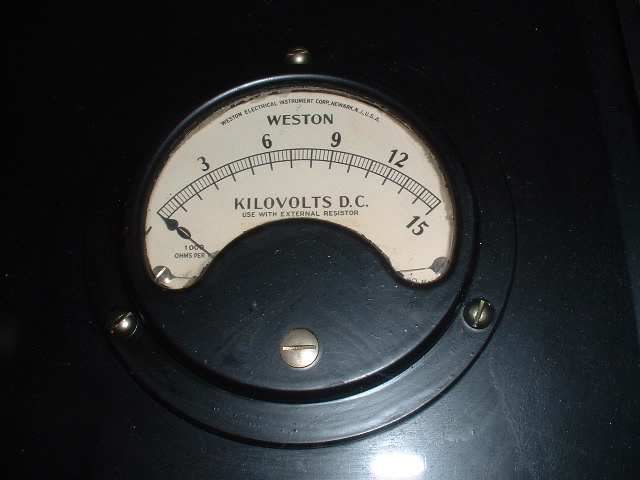
The meters are hand-lettered and
hand-calibrated Westons. I was told by the "old-timers" that once the unit was completely
constructed with blank
meter faces, that Weston would send a technician to do the calibration.
The oak frame is only for display of the original meter panel with original
cut-glass covering. The five meters in this assembly are:
Line Voltage 0-300 VAC
Rect. Fil. Voltage 0-300 VAC
Grid Voltage 0-300 VDC
Amp. Fil. Voltage 0-25 VDC
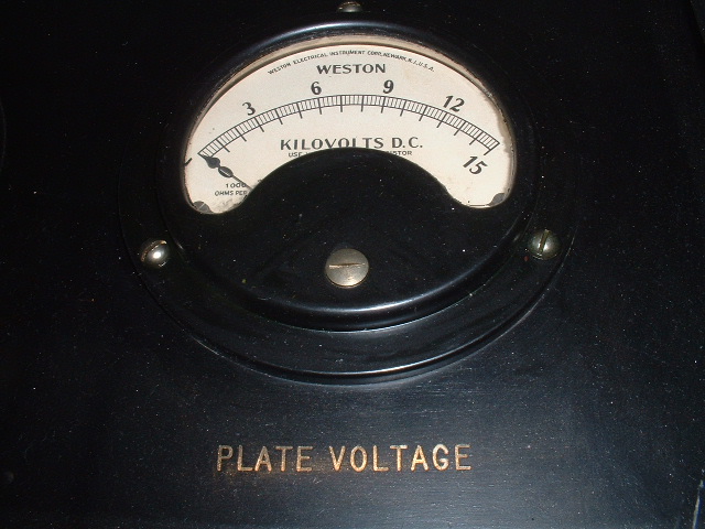
Plate Voltage 0-15KV DC
![]()
This is the Plate Voltage meter of the assembly, full-scale reading of 15KV. The plate transformer in this amplifier was in a large oil-filled metal cabinet, the transformer specs showing 15,000 volts @ 1 amp.
This Faraday-shielded coil assembly
was from the output circuit of the KRNT-AM 1KW transmitter. My
recollection was that this was from the impedance matching circuit.
The outer coil is 9" long by 5-1/2" diameter.
![]()
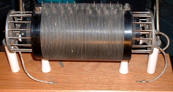
Note the "taps", connection being via machine
bolt. 
Very common with high voltage wires of the period,
the physical wire was run through miniature ceramic beads.
