Simple Radio PTT To Computer Interface Circuits
SSTV / ISSTV, PSK31, RTTY, CW, EchoLink, eQSO etc.
Digital communication modes represent one of the fastest growing areas
of interest in amateur radio, with the past decade seeing many
developments.
Over the past few years data modes like SSTV / ISSTV and
PSK31 have become popular.
In digital transmissions such as SSTV / ISSTV, PSK31 or even RTTY, the
ability of your own computer and radio to send and receive
various
digital modes is a real plus.
An interface unit allows one to transmit and receive these modes
without the expense of purchasing a separate TNC or DSP device.
A
regular sound card, as found in most of today’s computers, can
easily handle DSP functions. Conveniently, these interfaces are
designed to operate without an external power supply.
There are various circuits to enable you to build your own interface. I
have included here some simple designs that I have built, tested
and
which work very well considering their simplicity and economy. These
circuits will also perform well if you intend to run an Internet
gateway using eQSO or EchoLink software. Software for these modes is
freely available via the Internet,
Other PTT techniques make use the vox for PTT - but don't forget to
disconnect it or the inevitable Microsoft beep or late night mp3
might
create a surprise or two. It is best to avoid VOX switching but Many
new PCs have no RS232 either so I think we are soon
going to have to
find another way to drive our radios.
Digital modes can have a long transmitter duty cycle .Try to keep your
output power to 10 - 20 % of the max rated power. Disable
all the rig
compressors, DSP noise reduction etc.
Isolated Interface
Circuit 1 incorporates two 600-ohm audio transformers (T1&T2) and
an RS232 powered optocoupler IC1. Preferably use an IC
socket for IC1,
for possible quick replacement!
The purpose of the transformers and an optocoupler is to isolate the
transceiver from the computer, keeping the interference from the
PC to
a minimum. Ensure that the screening on the radio and the screening on
the PC are not connected together.
Stereo 3.5 mm plugs connect the line in and out on the computer
soundcard. Use the tip and earth only as in this application the sleeve
is not used.
To control the radio PTT an isolated signal from the computers RS232
RTS line is used.
If you have an available DB9 connector on your computer, use RTS, which
is Pin 7 and ground, which is Pin 5.
If you have a DB25 connector on your computer, use RTS, which is Pin 4
and ground, which is pin 7.
VR1 is a 1K linear potentiometer used to control the amount of audio
going to the mic and is adjusted for correct audio drive
to the radio,
usually converting line (0.5v) to mic (10mV) levels. The 1.2k resistor
(from the Line Out) can be changed to a greater
value if you are
troubled by the pot always being at the bottom or top of the range or
alternately by adjusting computers audio out
slider till the correct
level is achieved.
Operationally, audio levels are adjusted by the computer level controls
or are incorporated in the software you will be using.
The LED (high sensitivity type) is used as an indicator when the
interface is in the transmit mode.
It is suggested that the finished interface is put in a metal box and
that the grounding is taken from the radio side of the circuit.
Circuit 1
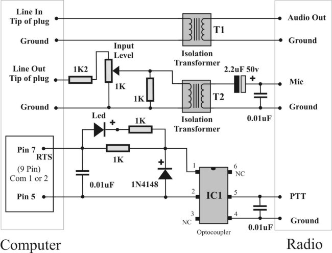
Components for Circuit 1
3 x 1k ¼ watt resistors - 1 x 1.2k ¼ watt resistors
1 x 1k Potentiometer lin – 1 x 2.2uF 50v capacitor - 3 x 0.01uF
capacitors
2 x (T1 & T2) 600 ohm transformers type 9000 RS Number 208-822
1 x IC1 optocoupler 4N25 RS Number 597-289
1 x Red LED (High sensitivity type) - 1 x Diode 1N4148 - 2 x 3.5mm
Stereo plugs
1 x 9 Pin D plug ( Com port 1 or 2) & cover
Screened cable - Project Box
Simple Interface
This circuit is very similar to Circuit 1 except it does not use audio
transformers or the optocoupler, but performs splendidly.
In this circuit RTS drives an open collector for the PTT.
You can use any general NPN transistor instead of a BC108.
Circuit 2
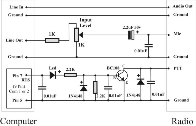
Components for Circuit 2
1 x 1k ¼ watt resistors - 2 x 2.2k ¼ watt resistors
1 x 1k Potentiometer Lin - 1 x 2.2uF 50v capacitor - 4 x 0.01uF
capacitors
1 x Red LED (High sensitivity type) - 2 x Diode 1N4148 - 2 x 3.5mm
Stereo plugs
1 x BC108 Transistor - 1 x 9 Pin D plug ( Com port 1 or 2) & cover
Screened cable - Project Box
Simple Interface for Handheld Radios
A handheld’s mic and PTT are normally combined, hence circuit 3
was designed and works admirably.
Audio levels can only be adjusted by the computer’s level control.
Stereo 3.5 mm plugs connect the line in and out on the computer
soundcard. Use the tip and earth only as, in this application, the
sleeve is not used.
Circuit 3
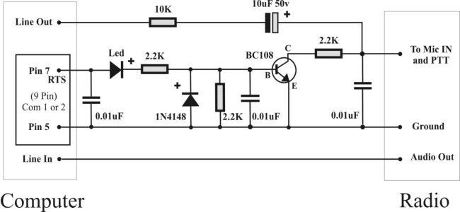
Components for Circuit 3
3 x 2.2k ¼ watt resistors - 1 x 10k ¼ watt resistor - 1 x
10uF 50v capacitor
1 x 2.2uF 50v capacitor - 3 x 0.01uF capacitors - 1 x Red LED - 1 x
Diode 1N4148 2 x 3.5mm Stereo plugs - 1 x BC108 Transistor
1 x 9 Pin D plug ( Com port 1 or 2) & cover
Screened Cable - Project Box
Glossary
DB9 9 pin connector (Found on computer COM ports)
DSP Digital Signal Processing
Echo Link Internet radio linking software
EQSO Internet conference by radio software
PSK31 Phase Shift Key 31
RTS Ready to Send
RTTY Radio Teletype
SSTV Slow Scan Television
TNC Terminal Node Controller