Click on thumbnails for larger pictures
|
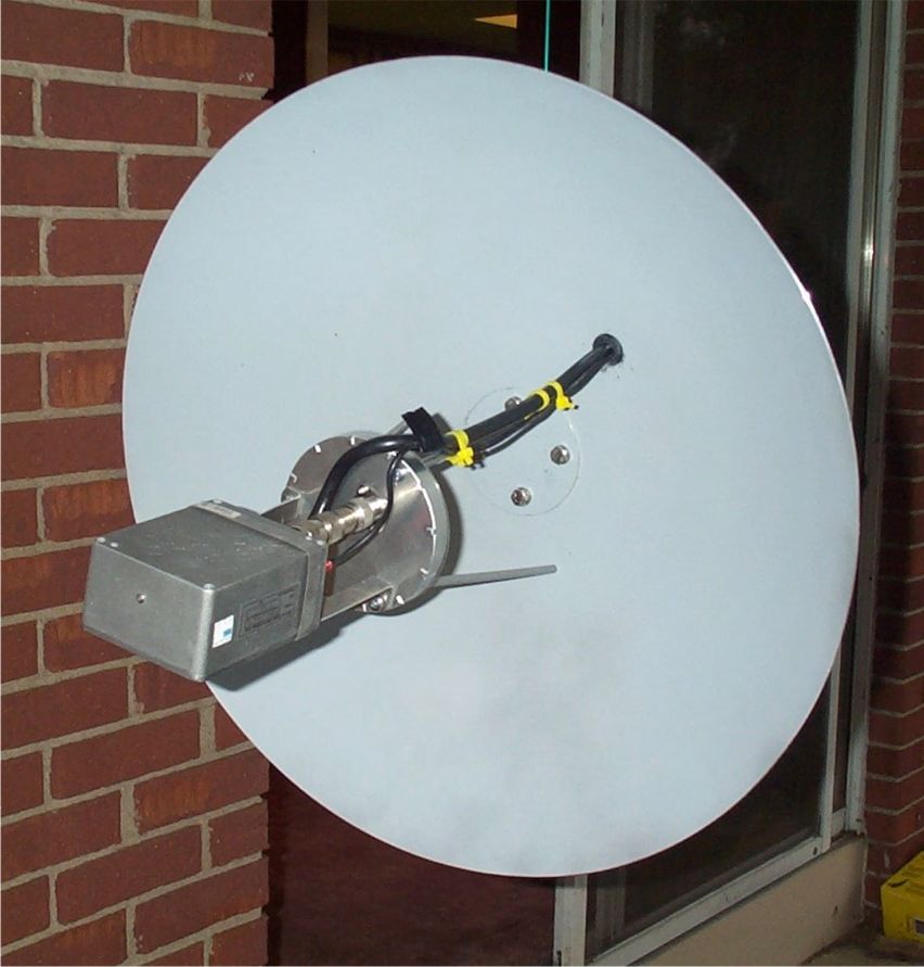
I started out my A0-40 station last year using a 24dbi BBQ dish horizontally polarized ( see my home page inset). This antenna performed remarkably well last fall for a newbie never on Satellite before. My only real complaint was the cross polarization spin modulated QSB which at times made receiving very difficult at even medium squint angles. This QSB also caused enough phase distortion on my beacon decoder that at times I missed up to 80% of the frames even with a strong s3-s5 carrier. After considerable research into what other successful hams were using I decided to try a G3RUH 60 cm dish with his matching patch antenna. I sent off to England in December and received it about a week later. Pay pal is great and I got great service and several stamps of Queen Elizabeth to add to my collection as a bonus.. I made no mods to the active part of the antenna system which is very well designed. On paper, the two antennas have about the same gain. The patch/dish is rated at 21dbi but that is circular. Subtracting the -3dB penalty from the linear antenna brought up the same S/N on the EXCEL link calculator but that can be very misleading when it comes to AO-40 QSB and spin modulation. I hope to see about another 2 db improvement in S/N or so and that should allow me to monitor the noise floor on the satellite when it is a half way decent squint angle. The low noise of the G3RUH antenna due to it's excellent match between the dish geometry and the patch beam width was one of the major selling features to me and I hope that intangible noise improvement proves the EXCEL Link model wrong. For some excellent experiments in solar flux observations with this antenna, check out this white paper written by G3RUH. I did make some mechanical mods to the G3RUH kit to fit my application which may be of interest to others and I will share these ideas here. The first mod I made was to replace the provided direct muffler clamp mounts
which required tightening from the inside of the dish with an L bracket I
happened to have for my old BBQ. I re-used the clamps but mounted them on
the L bracket 90degrees away from the suggested location. Any non corrosive L bracket of suitable strength could
be pressed into service. I experimented with several mounting
configurations for my
DEMI 2400-144
rx down-converter. I ended up using one
N-N male and one N-N female couplers back to back as an extender which allowed
direct in line mounting of the DEMI in the shadow of the patch and a very low
loss path into the converter. The spacing of the connectors on the DEMI
with it's drain holes etc did not provide many other options. I then reinforced the
converter now sitting on the N fittings with a pair of 1/8 inch aluminum
brackets and a stainless steel radiator clamp which I tightened around the
converter. I have had such good luck with the converter's weather proofing, I
was reluctant to drill any mounting holes. Anyhow the radiator clamp did
the job nicely. This stiffened the setup significantly since I did not
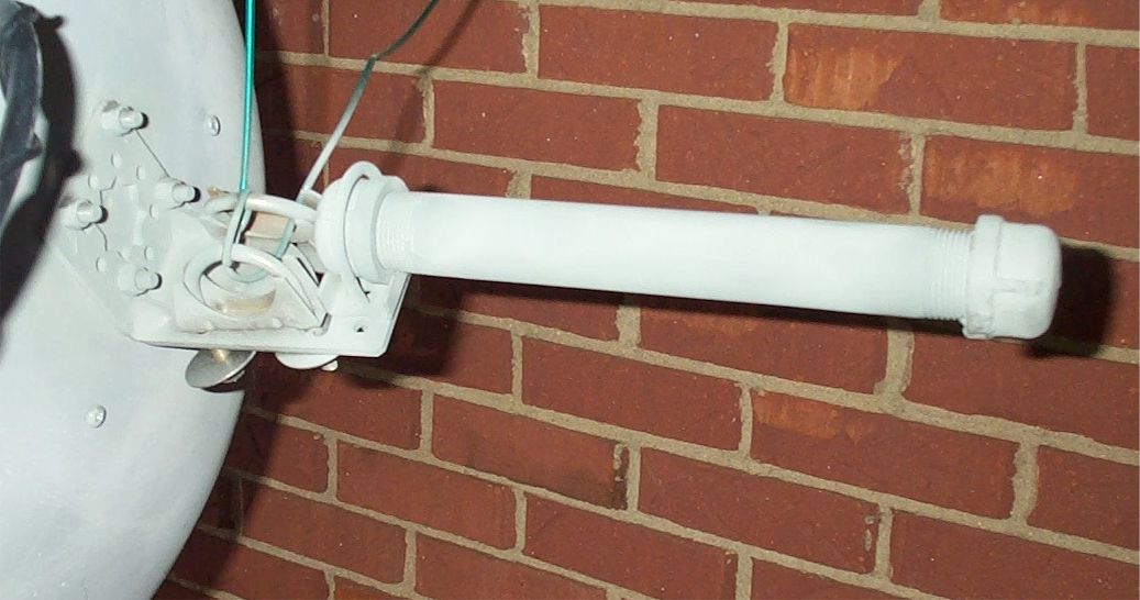
feel comfortable supporting it just with the just the N-N adapters. After running the LMR-400 2m and power interface pigtails out through
the standard feed hole near the top of the dish, I made a simple counterweight
system by using a single U bolt around a 10 inch x 1" galvanized pipe with caps
at both ends and mounted that to the L bracket. I obtained a supply of low
cost 1/4 oz fishing sinkers from a local fishing store for some lead and filled
the pipe with the sinkers and then heated it with a propane torch for
about 10 minutes. I then added additional sinkers until the counterweight
was sufficient to balance the torque of the cantilevered dish and converter.
It took about 3.5 pounds of lead plus the 1 inch fittings to balance the system.
When it cooled I coated the entire pipe and u clamp area with liquid cold galvanizing solution for some additional rust protection. For the final touch, I decided to build a shroud around the down converter to keep out snow and rain as well as add a cosmetic touch to drive the birds and neighbors crazy. I was able to locate an ideal cover at a local department store. It was a plastic round pasta container exactly the right size to slip over the converters and wrap snuggly around the outer rim of the patch. One small slit for the coax, a drain hole that lined up with the existing "pee" hole on the patch, and some RTV around the slit is all it took to seal this thing up.
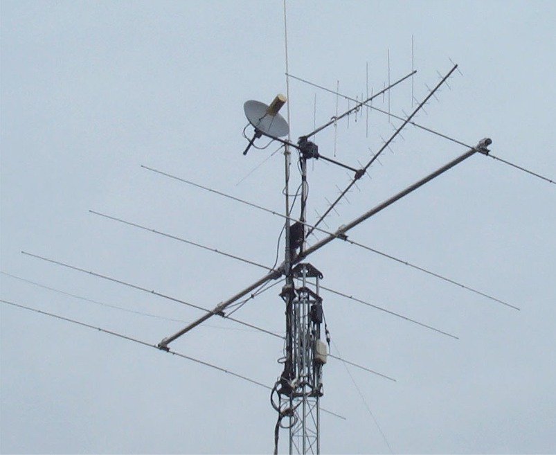
A coat of acrylic liquid gold paint was placed on the plastic outer cover to reflect heat and minimize the oven effect was the finishing touch. The gold gives the antenna a distinctive appearance as well. There may be some merit what that reflective coating does to noise arriving on dish side lobes versus reflections off the flat surfaces of the converter. It should have no effect to the main radiation pattern but what it does to reflected ground noise will have to be sorted out as I use it. It will also allow me to build an oven into it for next winter. I did notice some cold wx related drift ( 2-3 KHz) on my converter once the temperature dropped below 40 degrees F last winter. At all other temps, any drift was masked by Rx Doppler uncertainty models. I have no problem with thermal stability when it is warm, I will leave that next project to fall. But the shroud should l make that project a lot easier.. I mounted the antenna on the fiberglass cross boom on my existing tower which is a 44 foot Rohn 25 and uses a Hazer arrangement to allow working on the entire set of antennas at roof height. The dish shares a two axis ( split G800 Yahoo rotors) support structure for my 70cm x 21 element cross polarized yagi, a small 5 element 2 and cm antenna, a 2m collinear, and my 5 element Cushcraft 10 m mono-band beam.
Well it is Saturday afternoon and it is up. I just fired it up and A0-40 was out of range and still 20 degrees off of optimum trajectory for another 20 days or so. I did a quick sun noise S/N measurement as outlined by James Miller and saw about a 1.8dB ratio between max sun noise and hot sky 30 degrees off of the sun. This is not 2.5 dB as G3RUH is reporting but was a big improvement to me and warrants some more testing. With my BBQ, I never was able to see any significant S/N change with antenna pointed at or away from the old sol. This gives me a good feeling that my goal may be met or exceeded when I get a chance to hear the bird again. I have a lot of data from my PCR-1000 taken last year and am anxious to catch the bird and do some comparisons once the bird is back in 0/0 again. Hope I hear you all on A0-40 a little better than last year!
|