Micro Watt Meter

Back to 
Bernie's Bench
After recently getting back into building low power transmitters and RF circuits, I realized the need for a terminated watt meter. This is what grew out of that need: 
A 50 ohm terminated 0.5 watt and 5 watt meter, calibrated in RF watts. 

For my purpose, I settled on a two scale directly calibrated in RF watts, 
0-500 m.w.  0-5 W. 
The most unique part of this project is the method of calibration. 


Construction:

     The method of construction is not critical, however, here is an idea. I took a copper /glass board approximately 1&1/2 x 3 inches and some strips of copper board about 3/16 wide ranging from 1/2 inch to 1&1/2 inches long. These strips are made from double sided board. I cut the strips to the length of the circuit trace and positioned it on the base board. Then I sweat-soldered it to the base to form an insulated copper circuit trace. For ground, I used the surface of the base board. (See photo when it gets developed) 
 
 return to top of page
     I chose to use three 150 ohm, 2 watt carbon resistors for the load. That will come 
to 50 ohms. Then I went through a diode (IN192) to a trace with a by-pass capacior of .001 mf  to ground. This formed my peak reading detector. Next I went through a series resistor to the 0-500 uA DC meter. The value of this resistor was found by trial, since the movement of each meter could vary. (See schematic at end of page.)
the completed meter 
 

Calibration:

     The tool I used to calibrate the watt meter is a DC volt meter, like a digital mulit-meter. A volt source of 24 v DC and a good 10K ohm potentiometer. 
     The theory of calibration: 
     The formula for RF Watts or power is P=E*I. In our case, we are looking for the peak volt for an X watts with a constant load of 50 ohms. 

P=E(Sq)/R or E=(Sq Rt.) P R 
     (Note: I used a 500 uA meter from which I removed the scale, re-painted it white, then drew a base line arc with  marks for zero and max.
     The next step was to calculate a table of peak volts in relation to the units of Watts. Remember, the scale will not be linear. It will be a logarithmic scale compressing on the high end. On a scale of 0-5, One will be about midway. Because we have a peak-reading volt meter, and the power formula is RMS volts, we use Ep=Ea*1.414 (Where Ep=Peak and Ea= average) 
to find E for calibrating the scale. 
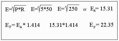
The following is an example for the 5W level: 


 return to top of page
     Now we can determine the value of the 5 W scale series resistor. First, I removed the 50 ohm load resistors so as not to load down the calibration voltage. Using the multi-meter, I set the 10K pot. to obtain a 22.35V DC at the input to the detector, or where the load was.  Then I selected a resistor to make the meter read full scale (5 W at 22.35 V).  Using a 500 mA meter movement, I came up with a value of 43.7K ohms. I used a 47 K and 200 K in parallel.  Then, for the 1/2 watt (0.05 W), or 500 m.w. the voltage came to 5 V and an additional resistor shunts the 43.7K ohms.  This will calibrate the full scale reading or base movement. This value is 18.6K ohm, made from 22K and 100K ohm resistors. 

      The following is a table of calibrated voltage to mark off the increments of the scale: 


Watts Calib. Volts
5 W 22.35
4 W  20.0
3 W 17.3
2 W 14.14
1.5 W 12.24
1 W 10
0.5 W 7.07
0.25 W 5
0.05 W 2.23
 
For the 1/2; watt or 500 m.w. divide the scale by 10 or move the decimal point left one digit. 
      (Note: any inconsistencies in the detector would be balanced out in calibrating the meter full scale.
      Now hook up your load resistors and input connector to the board. Meter for ground to the open end of the 5 W series calibrated resistor and a switch to switch in the 1/2 W calibrated resistor and you are ready to measure the 50 ohm output of your QRP rig. 

    (Note: I used a drafting pen to mark the scale and "Press Type" to label the values.

      Now that this project is completed, I am working on a low-power SWR/Forward power meter that can be left in line while using the rig. I will use the terminated Micro-Watt Meter as a tool to calibrate it. 
 

schematic diagram
return to top of page

 Back to Bernie's Bench Home | To QSL Home
This page last updated on 7/14/99
You are at http://www.qsl.net/wb4zba/meter.htm
Send email to Bernie at [email protected]
page created by trina