I sold my DX-302 but will still be maintaining these pages. I've collected my personal experiences as well as things people share about the DX-302 here. Maybe this will help you squeeze that little bit of extra performance out of your radio or save someone's (remaining) sanity someday...
CAUTION! The DX-302 and other electronic equipment contains dangerous voltages and can be hazardous (or, in some conditions, lethal). Only those with adequate training, equipment, facilities and experience should attempt to repair or modify any electronic equipment. You can destroy your radio and kill yourself! This information is believed to be accurate, but please verify and understand what you are doing before undertaking this type of effort. I strongly recommend having the service manual which is available from Radio Shack/Tandy for about $20. You might also want to consider paying an experienced technician (such as Electronic Service Pros) to do this work.
The DX-302's case is simple to open. On the back, remove the six screws (three top and three bottom) that hold the metal cabinet to the back plate. Once this is done, the metal cabinet will slide off the rear of the radio. Make sure the radio is unplugged and all cables are disconnected before doing this.
Replacement is just the reverse of this process. The only thing to watch for is that some of the smaller cables can be pinched between the chassis and the cabinet.
One performance issue that bothered me about the DX-302 was the tendency of its AGC system to "pump" when an AM signal was rapidly fading in and out. It finally got irritating enough to motivate me to pull out the schematic and do some research. I found a fix, but there are some trade-offs to consider. Read on if you're interested...
Good AGC design conventionally says that for AM signals, the time constant of the AGC system should be a few tenths of a second while for SSB and CW signals, a few seconds is a better choice. The DX-302 designers made a compromise for a time constant of 2.2 seconds in any mode. Since most of my listening on the DX-302 is to AM stations, I decided to modify this so the radio would be more responsive.
The good news is that the modification is fairly simple. The time constant is set by C351 (a 22 microfarad electrolytic capacitor) and R361 (a 100 kilohm resistor). As designed, the system has a time constant of 2.2 seconds. If you replace C351 with a 2.2 microfarad electrolytic capacitor you have a time constant of 0.22 seconds--much more suitable for AM signals. You do need to re-calibrate the S-meter (which also set AGC performance) according to the service manual or you'll experience some clipping on strong signals.
But what if you do listen to SSB enough to want a "slow" AGC setting for these signals? I first thought about putting a switch on the back to give me the two setting, but then I noticed something interesting in the schematic. The mode switch has a gang (Switch 3a) where the wiper is grounded. The only time this ground is used is to short out the AGC (which mutes the system) when you put the switch in the standby mode. So, I thought, why not use this to switch in additional capacitance in the USB/LSB modes?
If you look at the mode switch on my DX-302 from the front, the two terminals on either side of the nine o'clock position and toward the front of the radio are the terminals that are grounded in the USB/LSB modes. Tie these together and connect to the negative lead of a 22 microfarad electrolytic capacitor. Tie the positive lead to the positive lead of C351. All of this wiring can be done neatly in the under chassis. Make sure all conductors are insulated so nothing shorts out accidentally.
You're almost done now! In USB/LSB mode, the extra capacitor (let's call it C351b for convenience) is in parallel with C351 so you have a time constant of 2.4 seconds. But in the AM mode, the extra capacitor is open circuited, so you have a time constant of 0.22 seconds.
The only thing left to do is readjust the AGC/S-meter settings as described in the service manual. If you don't do this, you may get some distortion on stronger signals. As a temporary fix, this can also be corrected by backing down the RF gain.
This mod has made a world of difference in performance on signals that are fading in and out. Signals that would previously pump are now smoothly handled. For me, this was definitely worth the time and effort.
There is a problem with this. If you set the AGC/S-meter in the AM mode, when you switch to the SSB modes you will loose some sensitivity. This was worth while to me because I mainly listened to shortwave broadcasts. If your listening habits are different, this modification might not make sense for you.
The following modifications and information came from Greg Weremey of Electronic Service Pros. Check out their web site or e-mail them. My comments are in the green boxes.

1. The audio can be GREATLY improved. This radio has no low end response. By changing capacitors, you can get broadcast fidelity from it. Be sure to use a good external speaker too--the internal speaker is junk.
For my rig, the 3 dB (half power) points for the audio section were at 210 Hz and 6,350 Hz before modification. I bought a box of mixed capacitors from Radio Shack and did most of the mod with them. My values were equal to or higher than those in the chart above. After the mod, my frequency range was 120 Hz to 6,350 Hz. Below is a chart of the response. Click on it for a full size version. 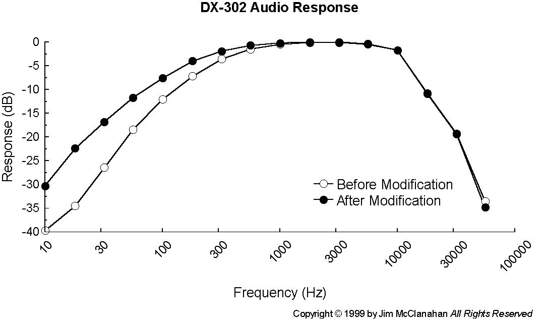 Even though the audio section handles the higher audio frequencies, the IF filters will limit the high-end response (as they should). It would be nice to have more control over the audio response. For me, that will probably soon take the form of an outboard audio filter. |
2. RF Gain can be increased. By changing / adding a resistor, you can modify the bias on the FET in the front end for more sensitivity.
I tried this one with a resistor substitution box and never found a value that made a significant improvement. If anyone else has any feedback, it would be welcome. |
3. Crystal filtering can be modified too! By using additional crystal filters (455 kHz) you can select a custom slope for the mode you listen to. I have 4 positions now.
I used a 455 kHz filter from a portable AM radio for the 10kHz bandwidth. You should try various filters, as some will cut the sidebands at 4-5 kHz while others will let 9-10 kHz through. The 4 kHz is the existing wide filter. The 500 Hz filter is from an old Collins CW receiver. The wide direct, is with no filter at all. It's just bypassed.
I did the wiring the cheap and dirty way. I used a DPDT switch to send the IF to the various filters. In one position I get filters 1,2 with the front panel switch. Then I reach around back and flip my DPDT switch, and I get positions 3,4 from the front panel switch.
The following modifications come from Frank Cathell in a news group posting from March 22, 1998. He passed them on from Kirk Wines.
1. Delete R219; it will greatly improve the RF sensitivity, especially on the lower SW bands, BC band and longwave. This may worsen intermod problems if you are near strong xmtrs so you will have to use the RF gain control to compensate.
R219 drives the base of Q206 the 0.01-0.15 MHz band and the 0.15-0.5 MHz band. This transistor shunts the output of Q207 (the second amplifier in the first IF chain) with C231 (220 pF). I haven't dug through all the details, but I would guess this was done because of strong signal performance. This mod "automatically" happens on all higher bands. |
2. Delete R227; it will cancel muting when you are tuning the MHz knob. This will allow for better peaking if the alignment is off and the tuning range will be extended to about 31 MHz (the digital readout will not show it , however).
When you tune the MHz knob, you are doing two things. First you are tuning a capacitor that selects which harmonic of 1 MHz you put into the first IF stage mixer--that is, what MHz band you are on. The second thing you are doing is changing what amounts to a rotary switch that drives the MHz indication on the dial. I would guess the muting was done to make this seem more like switching bands than tuning bands, but the distinction is subtle and their are good reasons (as pointed out above) to disable it. |
3. Remove one turn off of the lower winding of T206 (usually the gold colored wire); Re-tune the coil's slug to peak the sensitivity at 12 MHz (you may also want to re-peak TC205 at 28 MHz) and the 12 to 30 MHz band should show a significant increase in sensitivity.
I never tried this one... |
4. Optional Mod - will require schematic: remove C356 and re-connect the cathode of BFO oscillator varacter diode D311 to the right hand side of C340 ("hot" side of tuning cap VC4) through a 8 or 10pf capacitor. This will turn the BFO Pitch control into a fine tuning clarifier for the main tuning. You may want to re-check your LSB/USB "centering" alignment at L312. This is a far more functional arrangement than having a BFO pitch and LSB/USB selection.
I have mixed feelings about doing this. I kind of like being able to vary where my BFO falls in the passband of my filter, but fine tuning is also nice to have. I've heard that the older DX-300 actually had a find tuning control instead of a BFO pitch. Can anyone else confirm this? |
Not long after I got my DX-302, I used the code practice oscillator feature to introduce my son to Morse code. When I was done, I unplugged the key and went on to something else. The next time I turned on the receiver, it seemed to be stuck in standby mode. No matter what I tried, I couldn't get it to do anything.
After some serious pondering and looking at the schematic, I remembered using the code key. I plugged the key in again and with the key closed the receiver started working. What had happened is that the jack used to connect the code key was dirty and the internal shorting contact hadn't shorted. When I removed the plug this time, things worked fine. Replacing the jack is on my list of things to do next time I have the radio open.
If you make some type of modification or addition that requires an external switch or jack, but you don't want to drill the chassis, there may be a solution. The name plate on the rear covers a hole. I would guess that there are two holes for power cords (the grounded cord used in some countries, ungrounded used in others). Depending on which of the two holes was used, the nameplate was apparently installed over the other.
Copyright © 1999-2001 by Jim McClanahan All rights reserved.
All trademarks and brands are the property of their respective owners.