
ADDITIONAL DOME PICTURES
The additional attached pictures show the inside of the RoboDome before installation, pictures of the original plastic dome, how the RoboDome was installed, where the RoboDome controller is installed and the computer for my remote observatory.
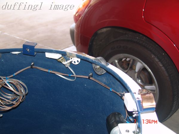
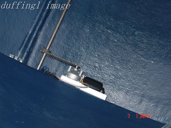
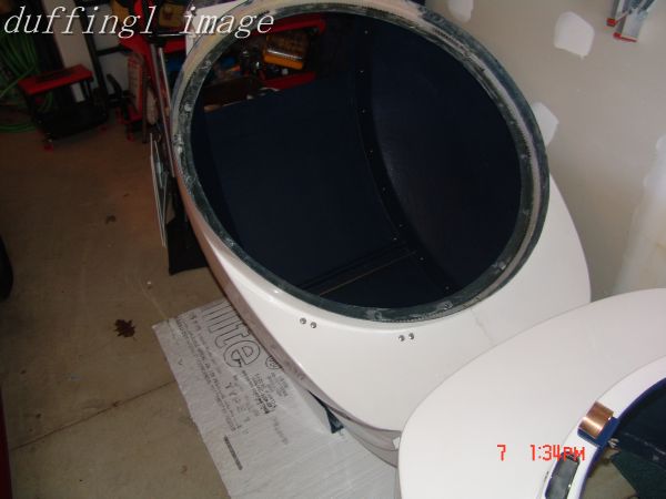
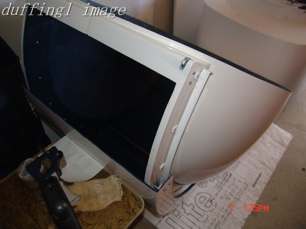
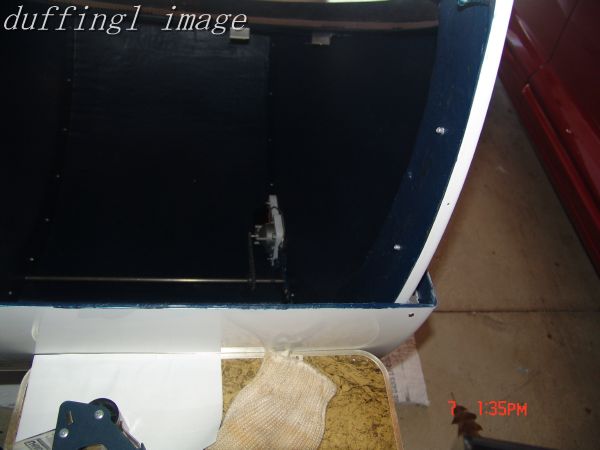
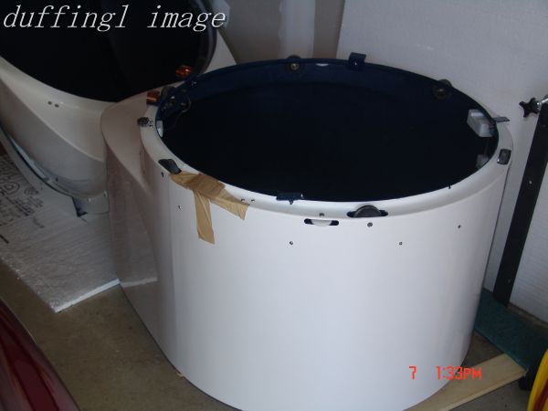
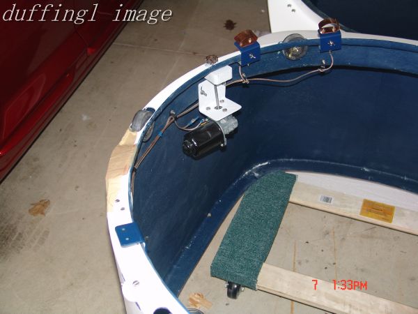
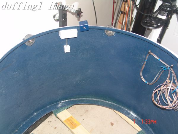
The above pictures are of the RoboDome awaiting installation showing some of the dome wiring and construction details
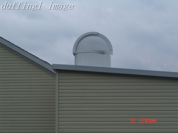
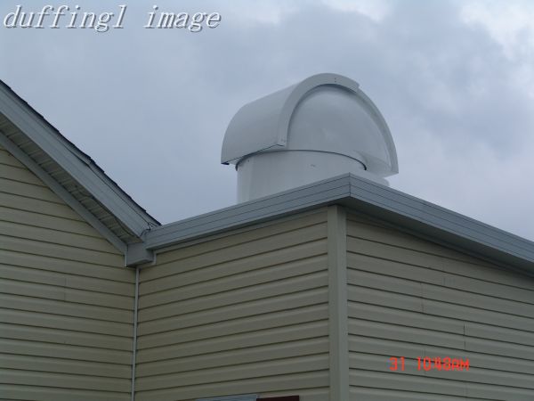
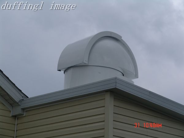
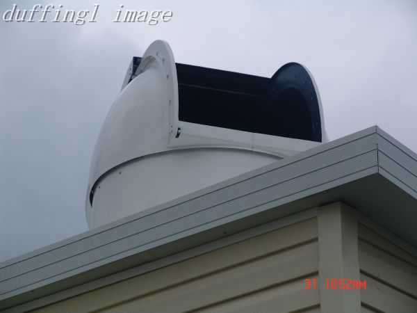
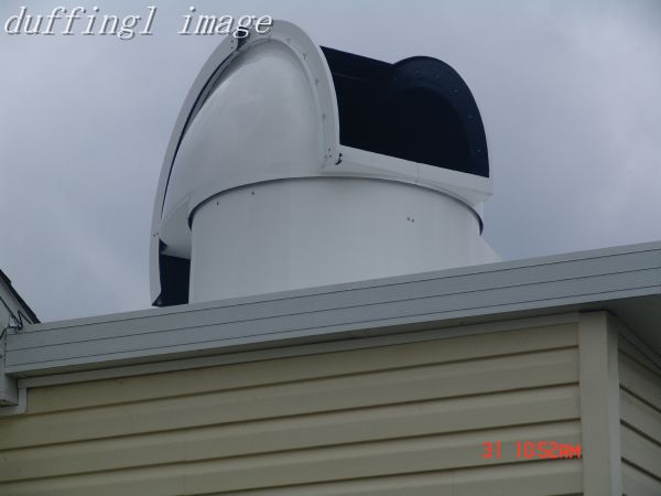
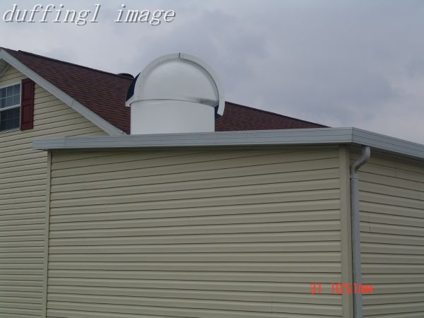
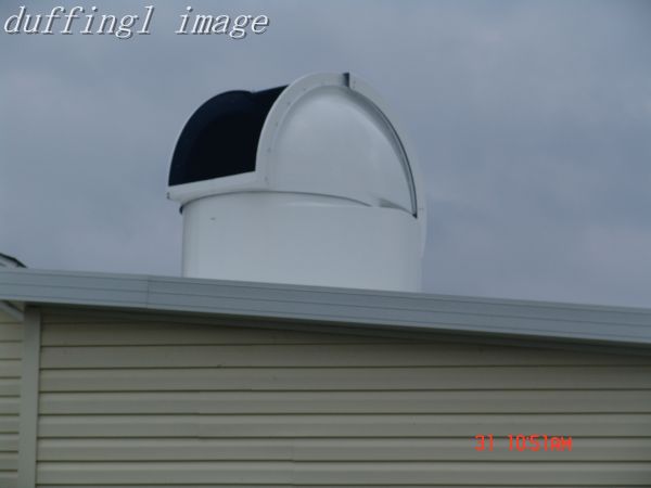
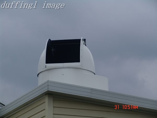
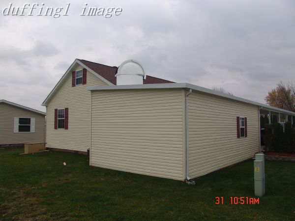
The above pictures show the RoboDome mounted on the roof of the garage. The fifth picture on the top row shows the RoboDome shutter all the way open to allow the telescope to point straight up. You can see that the shutter extends over the back of the RoboDome on the left side of the RoboDome in that picture.
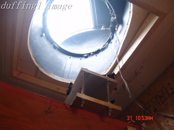
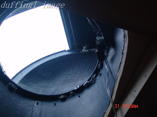
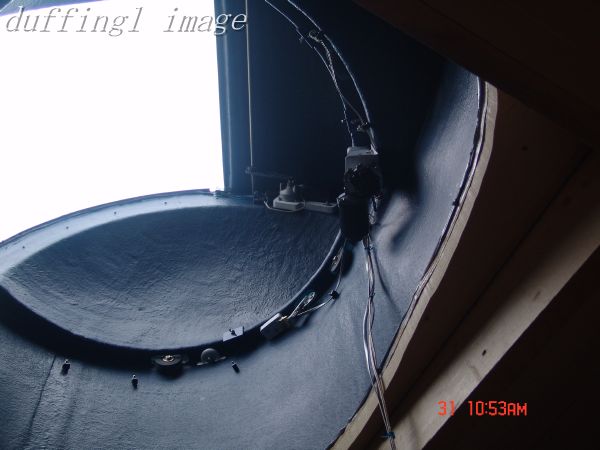
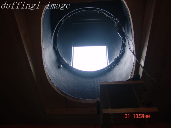
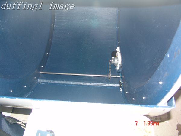
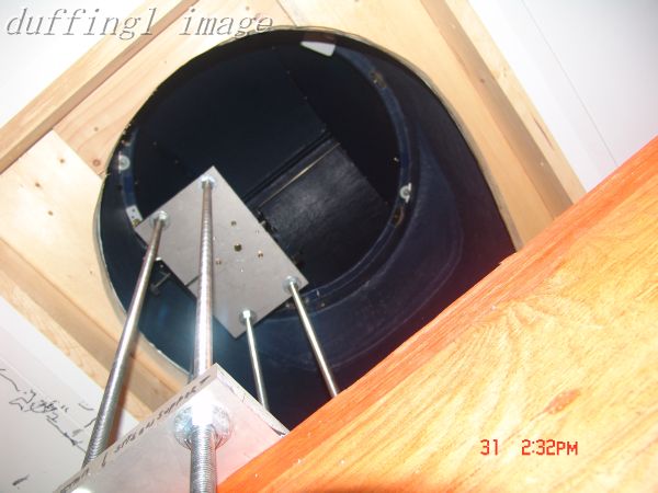
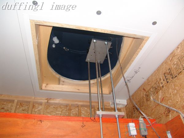
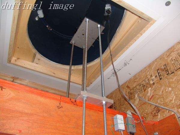
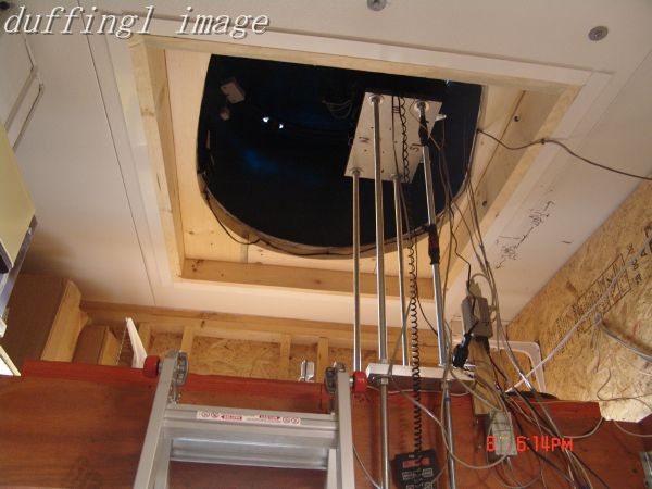
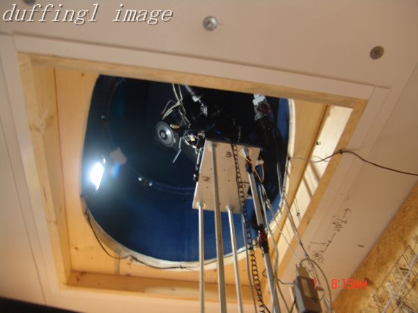
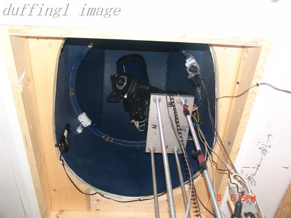
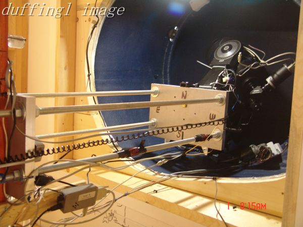
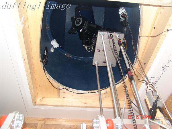
These pictures above are from inside looking up at the mounted RoboDome.
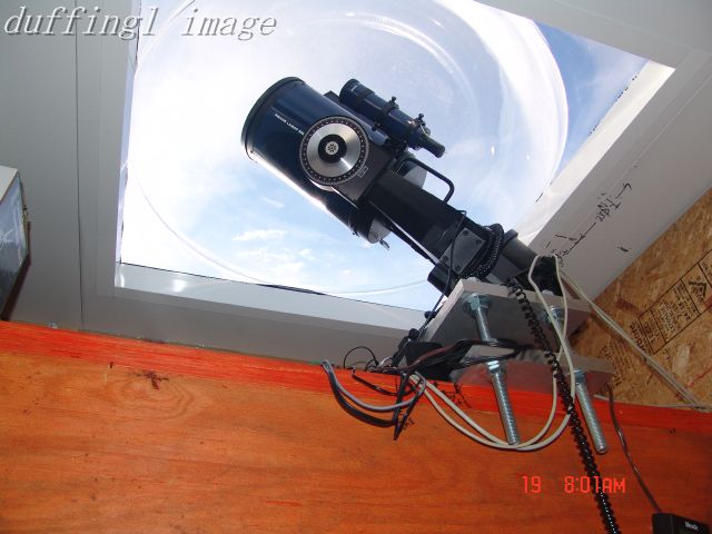
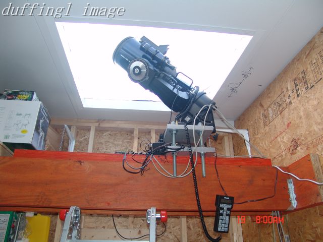
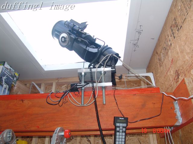
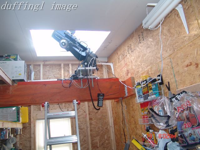
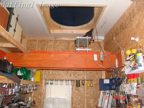
The above four pictures show the telescope mounted one foot above the wooden beam under the one inch thick 42 inch diameter plastic dome which got too hot during the summer time. The first picture shows the plastic dome quite well.
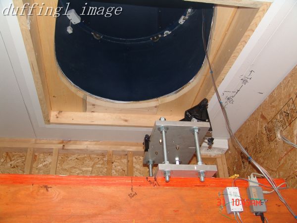
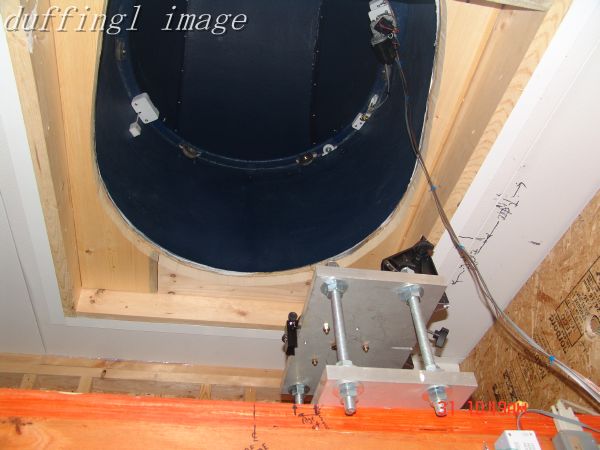
The above three pictures show the RoboDome installed but the telescope mounting plates in the original setup for the plastic dome, one foot above the wooden beam.
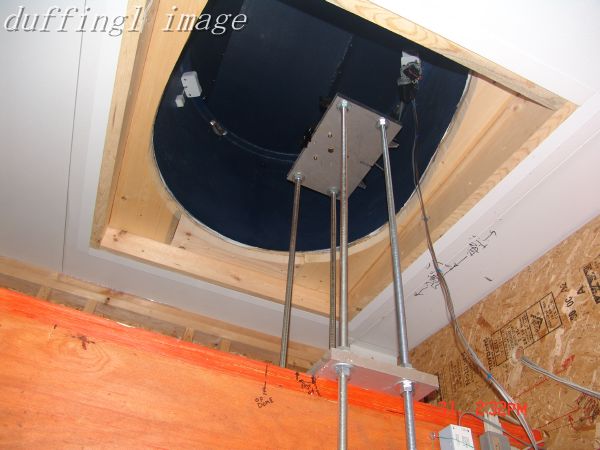
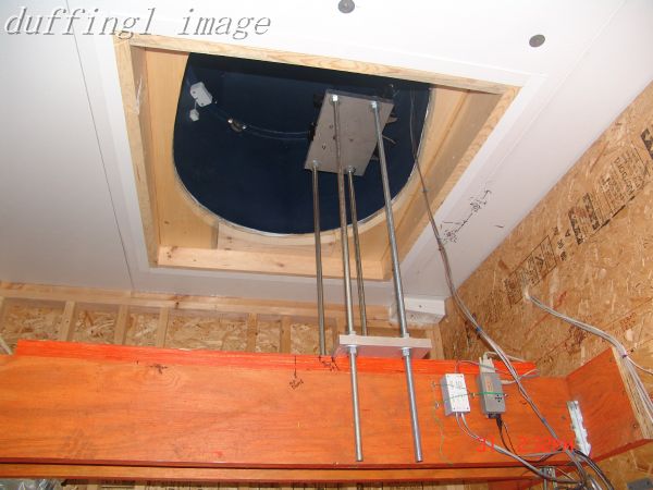
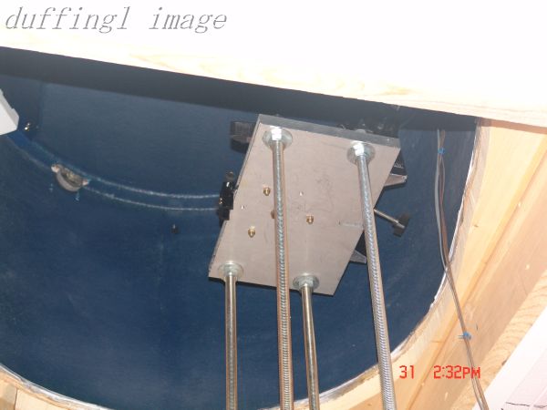
The above pictures show the dome installed with the plates in the four foot extended position but without the telescope installed. I had to climb up on the roof with the telescope to mount it inside the RoboDome through the open shutter. I should have taken the rotating dome off the RoboDome base to do this but no one would climb up to help me move the dome.
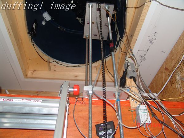
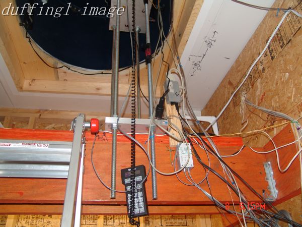
The above pictures show the plates extended to the four foot length to mount the wedge and telescope at the center of the RoboDome rotation and high enough to look at the horizon. Some of the wiring to the scope is shown.
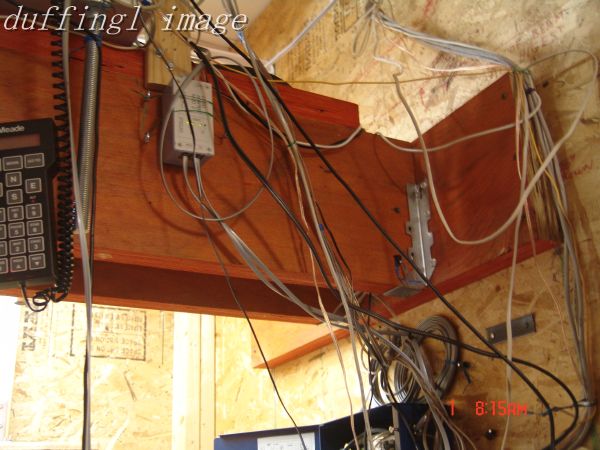
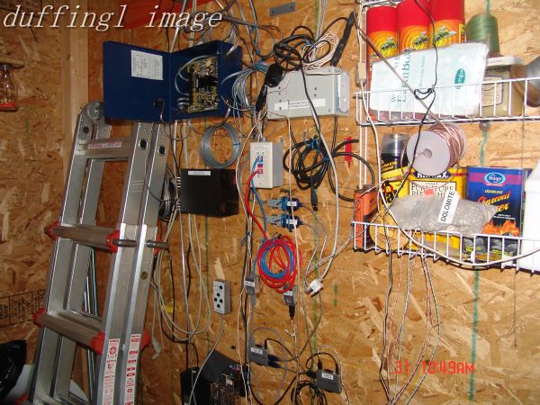
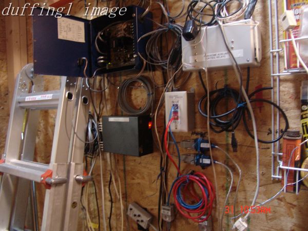
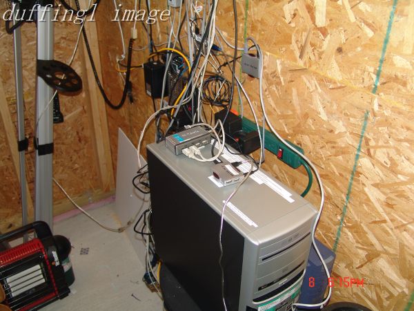
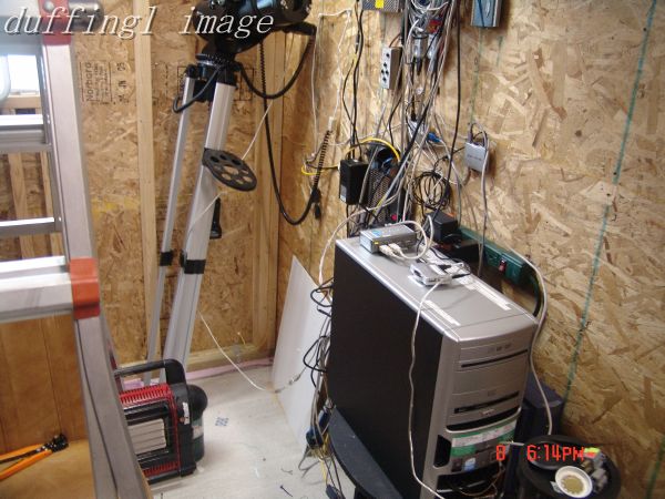
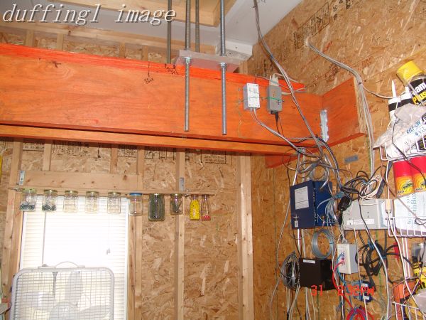
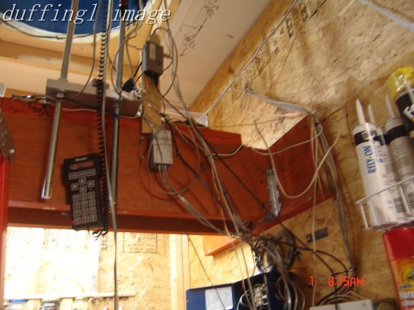
The above pictures show the various power supplies, the computer interfaces, and the computer itself. The RoboDome controller is the blue box with its cover open in the center picture.
The grey relay box in the top left of the center picture is for control of the SAC 9 power, SAC 4-2 power, the dew control and computer on/off. The relays are connected to my remote control room through CAT5 cable. I close a switch and the relay turns on the connected device and gives an indication when they are on in my remote control room.
The wires look like a mess but they are all low voltage control or signal lines and cause no interference. Once everything is finalized I will try to dress up the wiring.