Gates
Radio M-5078 Commercial SW AM/CW
Transmitter
Restoration Details
By John
LeVasseur, W2WDX
Copyright March 05, 2012

About this Article
My excitement over this radio is difficult to contain. Also I have for some time wanted to pen an article about a restoration we are working on in our restoration shop, with significant details. I wanted to write an article with not only the specifics of the particular restoration, but also including some basic "how to" information pertaining to restorations in general. Hopefully this article may give the novice restorer some useful information, show a restoration for something not usually seen for the more advanced, and be entertaining in general as well.
So go grab a cup of Joe (or your favorite beverage of preference), sit back, relax and read on. This is a long one ...
Commercial HF Transmitters
Compact HF Transmitters of the 1950's
Gates Radio is famous for having built large broadcast AM & FM transmitters. Many of these 1200 lbs+ behemoths have been lovingly restored and converted for Amateur use. The conversion of these transmitters is a labor of love for many. This article deals with the restoration of a product from a mostly forgotten and little known segment of the Commercial radio market. That being when companies like Gates Radio and others who normally built large transmitters, offered smaller lower power Short Wave transmitters for commercial use.
After WWII many companies went back to full scale commercial production after building solely for the war effort. The economy saw a boom. In this age with no satellites, no cell phones, no Internet (or even computing) and in some cases no access to telephone, HF phone & CW communication was used by many companies as a means to communicate to remote sites and/or over great distances. As Amateurs we understand the capabilities of SW communication, but for companies it was an essential part of doing business. Many of the types of endeavors that needed this type of long-range communications was mining, forestry, oil exploration, news media, remote scientific exploration, and others.
Since these radios were so crucial to these commercial endeavors, reliability became extremely important. So these companies who had large budgets turned to companies like RCA, Continental, TMC, and Gates Radio to build smaller "portable" radios that had the type of Continuous Commercial Service (CCS) familiar in the broadcast industry. They needed radios that could work under all conditions and do so reliably and continuously.
This ongoing article will show the restoration of one of these heavy-duty transmitters. More information will be added as the restoration draws towards completion, on an ongoing basis. All pictures are clickable links, to allow the reader to view larger higher resolution versions of the images.
Gates Radio M-5078 Transmitter
One of the transmitters built for this specification was the Gates M-5078. This small radio is a 50w input class radio, with high-level AM modulation and CW with full Break-in and limited PTT (more on that later.) It is specified to be continuously tunable between 2mHz-32mHz. It uses two crystals for frequency which are switchable from the front panel. It is housed in two small steel cabinets, one containing the RF deck and the other the Power Supply and Modulator. All components are conservatively rated for CCS.
The tube compliment is as follows:
- 6146 Final PA
- 6AG7 Crystal Oscillator
- 6AQ5 Driver
- 12AU7 (2) Mic Pre-Amp, Audio Driver
- 6L6 (2) Modulators
- 5R4 Rectifier
- OA2 (3)
All transformers are commercial grade Triad, except for Mod transformer which is a UTC CVM-1.
The two separate chassis are connected via a multi-pin connector & cable. The cable uses the standard Cinch- Jones type multi-pin connectors. The power cord is a two pin type. We were delighted to see both original cables were included.
Additionally, on the RF deck it also included a T/R relay which switches between two SO-239 sockets on the back panel. One contact is connected to the antenna socket and the other is connected to a receiver output socket, with the relay common being the Pi-network output. The relay allowed the use of a receiver on the same antenna without the need of an external relay (like a Dow-Key) and was controlled by the the PTT function. Another separate set of contacts is fed to a terminal strip for receiver muting.
Oddly, in its stock form the PTT function worked only via the "plate on" switch on the front panel and not by the microphone switch. The mic switch only turned the mic audio on and off. This particular transmitter was modified to include the normal PTT function by the addition of another relay and a transformer and some wiring.
The Gates as Received
This radio was purchased on eBay for $177USD in early March of 2012. It was not shipped fortunately since the person only lived about 35 miles from our restoration shop in Lindenhurst, NY. The image at the top shows the radio using the picture used on eBay by the seller. The images below show how the radio was received at that time.
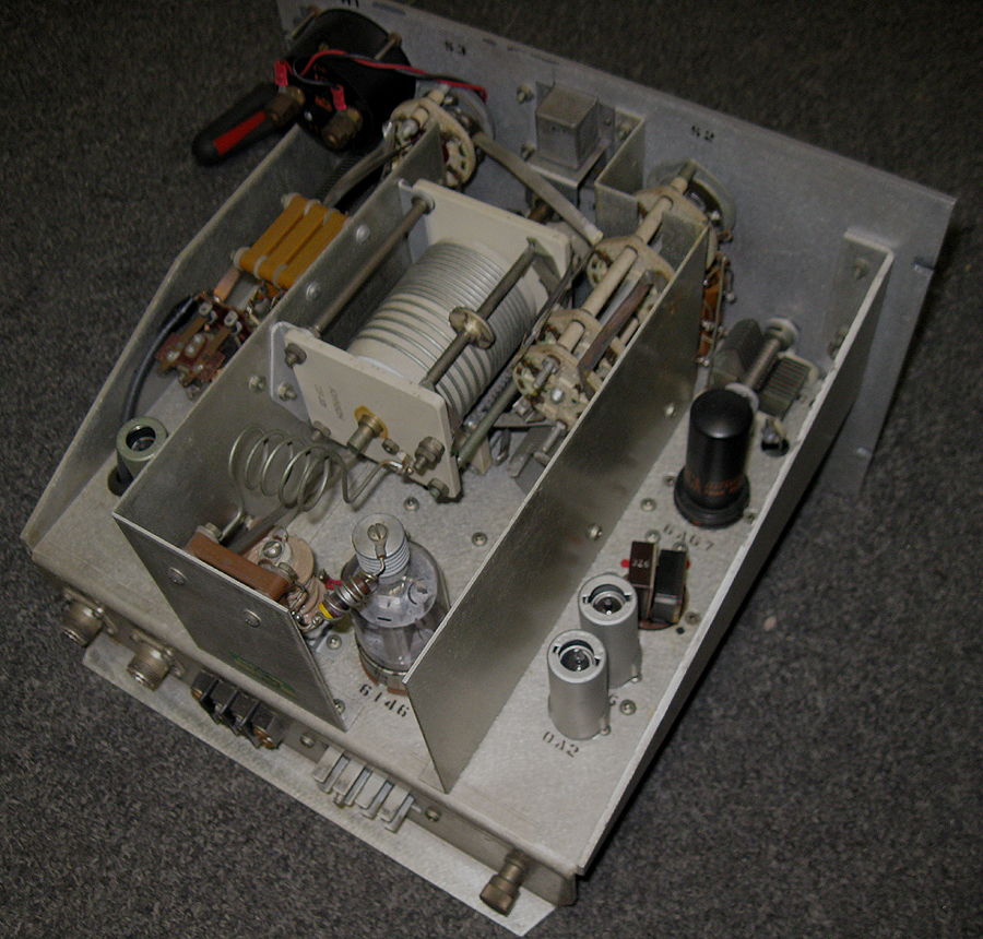
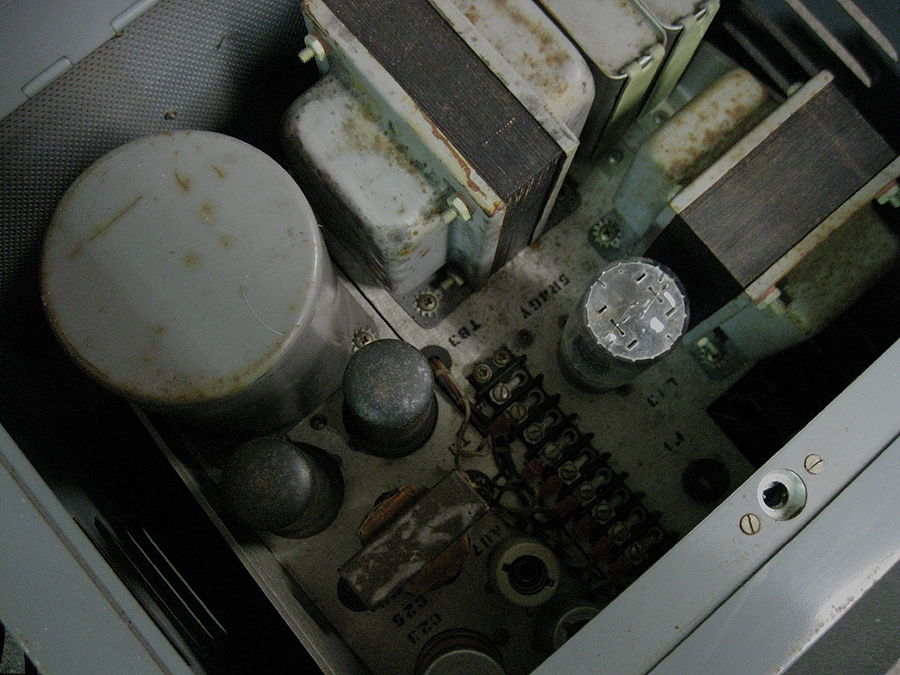
As you can see, the radio came in very clean state. Very little dust overall. The RF Deck internally was nearly new looking, all shiny and no signs of pitting or rust. The cabinet was also quite good showing very few scratches and little rust. The Power supply was a little worse. It did seem to have some signs of rust, and few more scratches. There was also some pitting and rust on the transformer covers, and along the laminates. I suspect it was located at some point on a floor in a basement or garage or some remote facility.
When you think of Gates you conjure images of large racks with huge chassis and mammoth weights. The chassis in this transmitter are small, measuring only 11"w x 10"d and are constructed of a heavy 1/8" thick aluminum with a small circular brushed finish to hide scratches. The front panels measure in at 12"w x 8"h and are also of the same material. The all steel cabinets are made to fit these chassis and are designed only for this transmitter (as far as I can tell.) Both cabinets together fully loaded weigh in at slightly less than 80lbs. The RF deck chassis is smaller than a Johnson Ranger chassis. Not your typical mammoth Gates!!!
After inspecting the radio and being satisfied it was in very good shape, I decided to try hooking it up. First I tested the transformers to see if they were all good ... Pass. Now the voltages ... Pass. Couldn't find any components that visually looked bad or burnt ... next. I hook it up to a dummy load and ... Not surprising I find it's fully functional. It worked. I know I took a risk, but I figured it's a Gates. Might as well see. Besides I was gonna restore it anyway!!! This is a testament on the build quality and the CCS parts selection by Gates to build high quality and reliable radios for this market. Fifty-four years later and it still works fine.
(Sidenote: The radio tuned perfectly on 1.885kHz with no problems, so it does work on 160m. I also tested it on 75m & 40m. Again no problems.)
Front Panel Work
Dated: March 8, 2012
So now I begin the work at hand. I decided to first work on the front panel. There was what appeared to be slight surface pitting in the paint, more so on the upper left hand side. After working the panel a bit I discovered it was easier to remove than I thought. The paint used by Gates is much harder and denser than other paint I have come across on front panels, even the R390a's I have worked on. Below are before and halfway through images of the front panel.

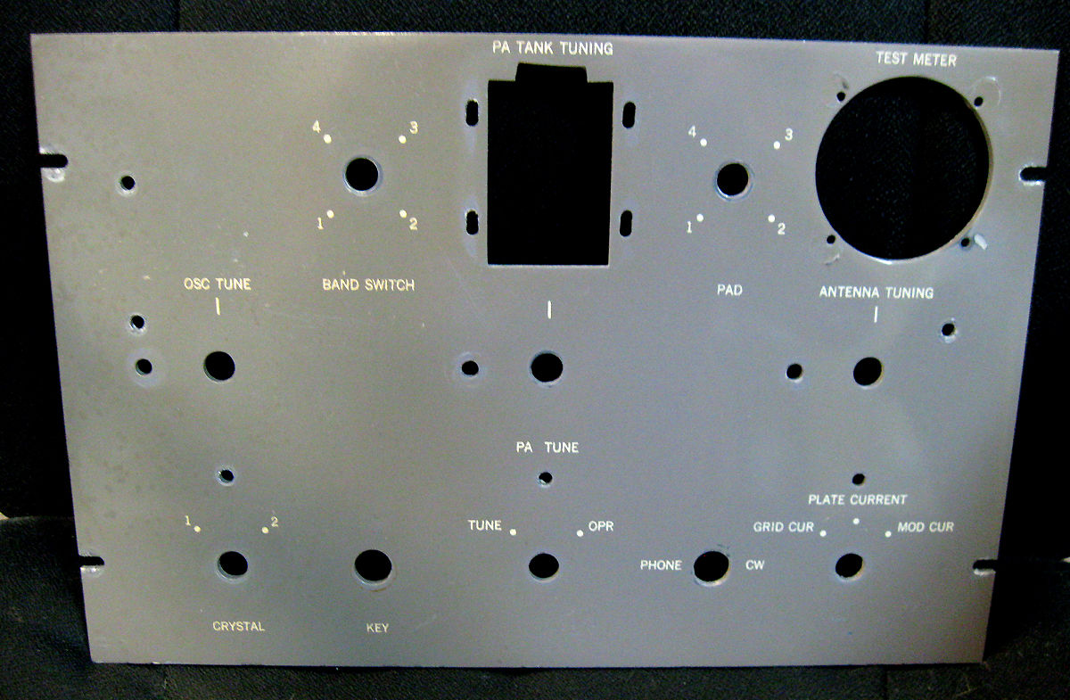
The image on the left shows the front panel after being removed from the radio in its original state. The image at right shows the panel after the working on the right side of the panel only. You can see the usual browning of the paint on the front panel. In most cases on painted panels this not only surface gunk, but also is set into the paint itself. If you are not going to repaint a panel, you must remove the oxidized layer of paint in order to completely eliminate this browning.
On flat painted panels, I use a technique that simply involves scrubbing the panel with a stiff brush after spraying the surface with Windex. In the image on the right the entire panel has been scrubbed numerous times with Windex. However, as you can see it doesn't totally remove this brownish layer. That's where the next step comes in.
After several scrubbing steps with Windex, I begin to compound the panel using various grades of automotive compounds, and finally ultra-fine polishing compounds used for Clearcoat. Many numerous clean cloths are essential here, do not use paper towels. They will leave very fine scratches in the surface. Cleanliness is very important as well. Do not use cloths to many times (the reason why I say have many.) A final chamois really brings out the shine when done. The image above shows only the first once over with compounding on the right side of the panel. Numerous subsequent steps, with gradually finer polishing compounds will follow until the color and finish is consistent across the entire panel.
Using a machine is not recommended here. Do this work by hand! You may find that while buffing away with your power tool, you may end up with no lettering or even worse no paint in spots. Again do this work by hand.
I cannot emphasize too strongly that when using this method you must be very careful of the silkscreens so as to not apply so much force as to harm or remove them. It is very easy to buff them into non-existence. Use minimal force, letting the compound do the work, and pay attention. This method works very well removing brown soaked in patina and tobacco stains, removes any oxidation of the paint and in removing any pitting or flaws in the surface of the paint.
The Final
Product

As you can see the results are quite good. We also did the same for the Power Supply front panel as well as the cabinets. Now we have front panels & cabinets looking almost good as new!!!
Getting into the Chassis
Further along we will show how we remove and repaint transformers & oil caps, how we reform electrolytic capacitors. We will show you some simple modifications that can be done with almost any AM modulator to improve audio bandwidth and methods for aligning and testing restored AM transmitters. We'll even show you how to "sweep" an AM transmitter to test its audio frequency response.
For now though, let's explore some the work we are doing on the RF deck and some techniques and knowledge you can use in any restoration.
RF Deck Overview
Since this radio is working, and since the RF Deck chassis is so clean, fully disassembling the RF deck chassis is not necessary. So on the top side we will do some basic house cleaning and maintenance, including cleaning and lubricating the mechanical components. The RF deck in this transmitter is very similar to many boatanchor types. Its circuitry is not unlike other AM transmitters of this wattage & time period. However there are significant differences that are uniquely related to it and its CCS design.
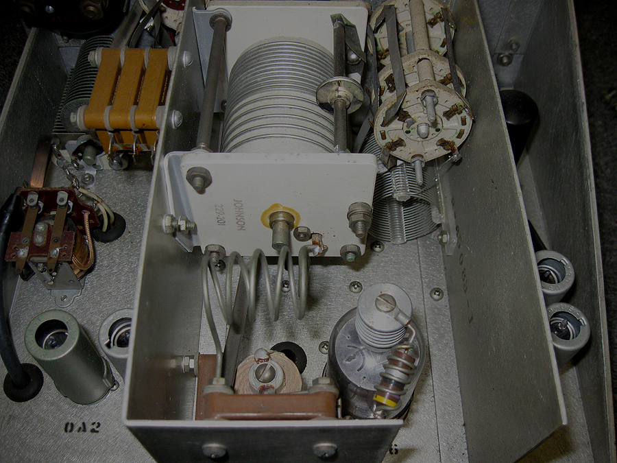
The Gates M-5078 is over designed, by Amateur standards. Some of the features that make this transmitter so reliable is the use of components that exceed the CCS rating for the circuits involved, particularly the transformers (we'll get into that when we explore the PS/Modulator deck.) For example, the Pi-network output uses a roller inductor, several fixed inductors, several switched high voltage capacitors (loading) and variable capacitors.
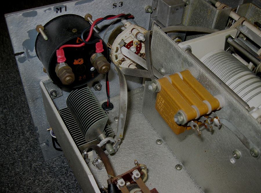
Of particular interest are the three large capacitors that are used in the loading section of the pi-network. These are large hi-grade mica capacitors switched in to add capacity to the variable loading capacitor depending on the antenna load and frequency. These are big, are switched through a large ceramic rotary switch and connected with solid silver straps (used throughout the transmitter for high-level RF.) The maximum voltage rating of these caps is 1200v, way more than is normally found at this power class.
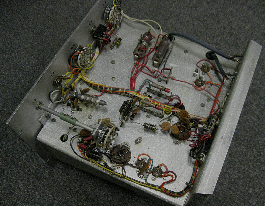
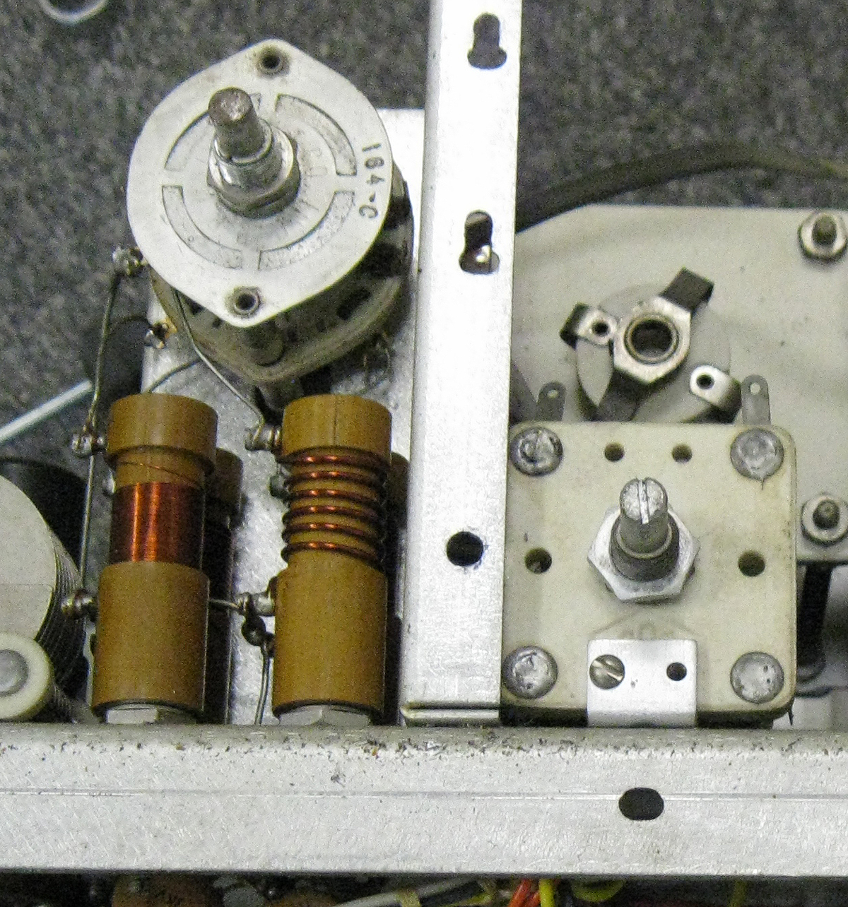
The large Johnson roller inductor is conservatively rated for use in transmitters up to 500w. Again overkill, but inline with this transmitters CCS design goals. Another large fixed inductor can be seen next to the roller inductor and under the over sized four position band switch. This band switch is used to switch into series this additional inductor for the lowest band. This switch is also used to switch four large tuning coils that are part of the oscillator tuned output leading to the RF driver. Again these coils are over sized for the low level RF they are handling. You can see these coils in the image below. For perspective, this is looking at the chassis from the front with the front panel removed.
So next we will show some the things to look for on issues such as switches, pots and in this case, roller inductors. These things will improve the performance and help maintain the long-term working reliability of any radio.
Lubrication
There are endless discussions about the many different products folks in the hobby have used for lubrication of the various moving parts in boatanchors. Much of this is learned by doing and experimentation, and that's fine. And while this is acceptable for most, I am one of those guys who likes to learn the science and follow some basic engineering practice. One of those practices is: Solving a problem by creating another is not good engineering practice. Basically understand the problem, research the correct solution and apply that solution.
One always hears about Hams having scratchy pots, knobs that don't turn freely, and other sticky mechanical problems. Even after "restoring" their radios. While many can tell you every specification of every tube ever made, and how to drive them, they cannot say much about lubrication other than they slobber any old stuff on whatever part. And repeat this process over and over and over ... Electro-mechanics has never been the strong suit of most Hammy Hambones!!!
Most times the reason for this is poor lubricant choice, and a lack of understanding the chemical properties in relation to the specific parts being lubricated. Pots do not get the same lubricant as gears, which do not get the same lubricant as variable capacitors, which do not get the same lubricants as panel bushings, etc. For some it's WD-40, Tuner Wash & 3-in-1 Oil for all. Yikes!
Without going into a complete dissertation on lubricants (three paragraphs in already, who's to say I haven't) choosing the correct lubrication will help prevent the aforementioned frustrating reliability issues for years. Yes ... years. Below is a list of applications and the correct types of lubricants for the job:
- Potentiometers: Caig FaderLube or similar products made specifically for Pots. Nothing else, no WD-40 ever!!!
- Variable Capacitors: Again Caig FaderLube is good. Also any light synthetic machine oil.
- Roller Inductors: Caig De-Oxit on the coils, roller contact & other contacts. Bearings light synthetic machine oils.
- Panel Bushings: Heavier synthetic machine oils (90W.)
- Gears: Light synthetic machine oils
You probably noticed the emphasis on the word synthetic. Synthetic oils lubricate as well as any other lubricant. However, the advantage for our uses is two-fold: one, they do not degrade and dry-up and turn to gunk as quickly. Two, they do not break down from the higher temperatures found inside most tube electronics. And any good grade synthetic machine oil will work well for our uses. Be aware they do come in different viscosity levels as well. Radio Shack actually sells a very good oiler with a good grade of light synthetic machine oil. Avoid automotive engine oils, even if synthetic, since many contain detergents & additives which can actually be corrosive to some electronic mechanical components.
Lithium grease should be avoided as well. It does have a nasty tendency to harden over time, squeezing out of joints and rendering its usefulness as a lubricant nil. Also the same goes for standard greases. OK ... Let's just eliminate all grease. Yuk!
Let me just touch on things like FaderLube and De-oxit. FaderLube is a lubricant, De-Oxit is a metal oxidation inhibitor. As a result their uses are distinctly different. As I have mentioned in other threads on AMFone.net De-oxit should not be used inside potentiometers. Overtime it will break down the carbon resistive material since it chemically reacts to it as oxidation. It's lubrication & cleaning properties are also limited. FaderLube is a product that is designed specifically for potentiometers. It will not break down the resistive components (carbon or plastic) and provide correct lubrication for the pot and its mechanics. Both should be used sparingly, as should all lubricants.
A good rule of thumb is to not use spray type lubricants. Hosing down your radio with lube ... It be bad mojo mon!!! While you can get the lubrication on the part, most likely you will also get it all over everything else. This includes fluids like the Caig products. Always look for packaging that include fine tips or needle applicators. A tiny amount of lubricant goes a long way. Using applicator tips and putting the lubricants where you need them should always be preferred. It will save you on clean-up time, stop dust from collecting on wet spots you couldn't reach to clean up, and gets the lubricant only where you need it. You also save money since you're not wasting lubricants.
Roller Inductor Cleaning & Lubrication
The Gates M-5078 uses a roller inductor on the pi-network on the output to allow for continuous tuning through its range. A great feature! However well all know that keeping them clean, properly lubricated and corrosion free is important. The technique shown here will of course be useful in maintaining any roller inductor and keeping it rolling on smoothly and reliably for years.
Gummy
Bears?
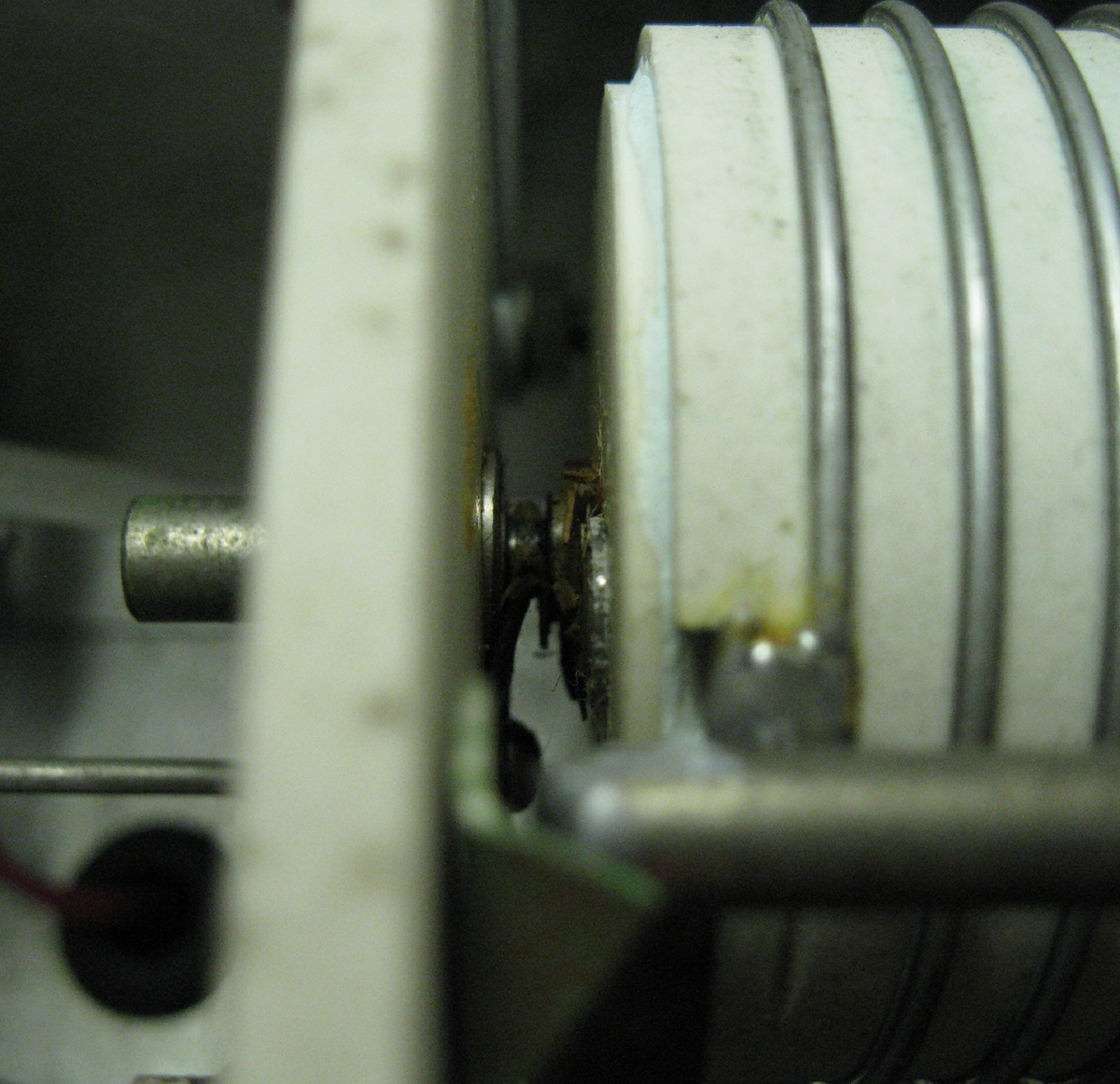
In the above image you can see the roller inductor for the output network on this transmitter. Here grease was used as a lubricant for the bearing on the inductor. This grease has, over time, turned into ... well it has the same consistency of a gummy bear. The joint was stiff, and had no lubrication. One could use two choices on this, light synthetic oils or FaderLube. I chose the latter since it does improve the contact point electrically while providing lubrication.
Adding Lubrication to
Roller Inductor

After cleaning out the gummy bears using 91% alcohol, the joint is lightly lubricated with FaderLube. This is the 100% solution with the very convenient needle tip applicator. As always, use lubricants very sparingly and wipe up any excess. This lubrication will last a very long time. It is very easy to reapply a drop in the future if need be once cleaned up of the Gummy Bears.
Just a Drop or Two Will
Do

The next step is to clean and stabilize the inductor coil and moving contact. The entire roller assembly should be removed and cleaned in 91% alcohol. After it dries reinstall it. The coil itself should never be sanded, burnished or rubbed hard. Wipe it clean with alcohol, then apply a few drops of De-Oxit here and there. With a clean fingertip, rub it lightly over the entire length of the coil. If you find a spot with a little more corrosion rub it a little more till the entire length feels smooth to the touch.

Next it is important to wipe the De-Oxit off. It works at a molecular level so wiping it off does not diminish its anti-corrosion and conduction enhancing properties. Removing it helps prevent dust from adhering to any excess making the roller inductor less reliable. The next step is to take a balled up piece of paper towel, and while spinning the inductor let the towel ride the full travel of the coil. Repeat this until you are sure no more excess De-Oxit remains.
Next do the same for the round roller contact wheel, wiping off any excess. For the rod and bearing of the wheeel, use FaderLube or light synthetic machine oil sparingly. You may also want to put a drop of De-Oxit on the contacts of the coil near the central bearing. Also on the tensioning springs and the screws that hold them in place and also where the screws make contact with the solder terminal.
BTW, these bottles are of the 100% formulas of the Caig products. I have had these bottles for six months now, use them everyday and they are nearly 80% full. They certainly are not inexpensive, but these bottles will last for many years for the average Ham. Versus the spray bottles which go empty in short order. The needle applicators seem clogged on these to someone who has never used them. Leave them be. These tips are designed to allow a small drop to come out slowly with light pressure combined with capillary action. The tiniest amount is all that is needed for the liquids to do their job.
(Sidenote: The images here where taken before the actual work was performed, you can see some of the gunk still on the roller inductor. It's hard to do the work with one hand, and take pictures with a camera with the other. So, the images above are just for reference. Damn ... my hands are getting wrinklely!)
All text and images contained herein are under strict copyright.
Reprinting or publication in any medium is not allowed without express written consent of the author.
Copyright 2012 John LeVasseur