| Homepage / | W2WDX Station Info / | Modes / | Other Links |
| New Additions / | QSL Info / | Amateur Articles |
This device serves two purposes. One (1) being the suppression of lightning and two (2) the reduction of noisy static impulses. Let me say this, the design for this circuit is not original nor mine. It was originally patented in a slightly different form by Mike Koss, W9SU (SK). I simply used this concept and expanded upon it to a great degree in application. In my design the components are much larger higher capacity devices. Also in place of tiny gas discharge tubes I use large horn gap spark gaps.
Circuit Design
Essentially, the circuit can be described as a DC coupled, DC blocked spark gap arrester for balanced transmission lines. It is a combination of what Mike Koss came up, along with other lessons I learned from broadcast station construction I have seen. Most lightning suppressors designed for coaxial cable systems use a gas discharge tube. In the Alpha Delta design, these tiny little devices are shunted from the center conductor to ground, nothing more. In the Polyphaser it is the same with the addition of a DC blocking capacitor in series with the the center conductor. However, this configuration does not allow for dissipation of static, which builds up and eventually causes the gas discharge tube to fire. If static is particularly high the tube will sit there and "spit" continuously causing sever receiver hash.
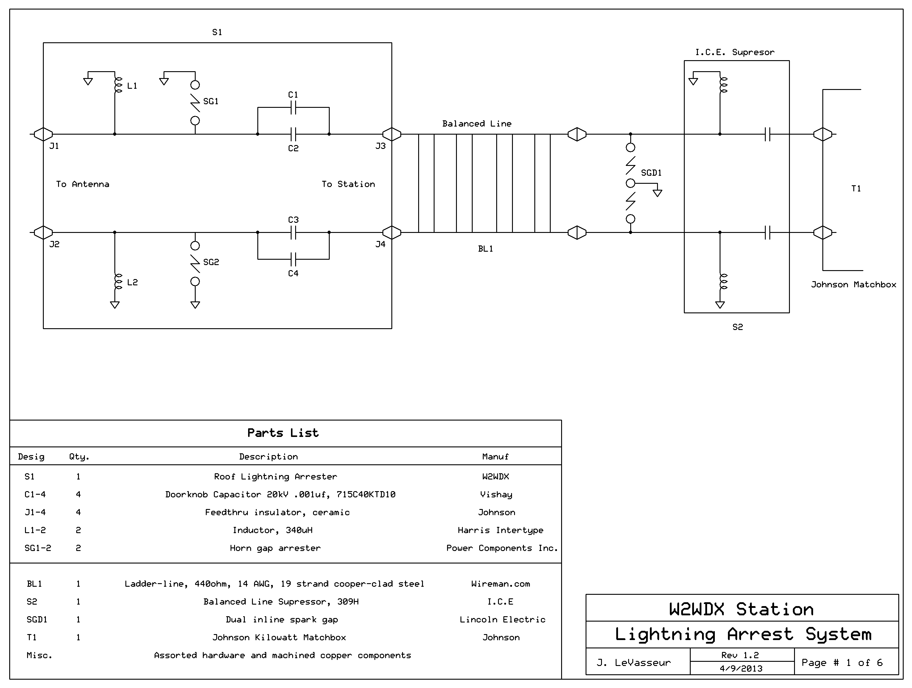
Click on image for larger view.
So obviously some type of DC shunt is needed, however it needs to be invisible to HF and still pass DC and low frequency AC. So an inductor is actually needed. Also the use of a DC blocking capacitor was called for. The inductor is on the antenna side and the series DC blocking capacitors are on the station side, with a large horn spark gap in between serving in the function of the gas discharge device. Then all of this is doubled for use on each leg of the balanced transmission line.
For me I was building a very large extended Double Zepp on the roof of a 24 story apartment building in New York. Large scale lightning suppression became important to gain approval from both the building Board as well as the New York City Buildings Department. Since I am a New York State certified PE they would accept anything I signed off on, as long as they saw it was substantial. So I went to work ...
The Components
First was the core of the system from a lightning perspective. Since I understand that nothing is 100% effective when it comes to lightning, I went about looking for something that would mitigate the risks as best as possible. I looked at commercial broadcast solutions, electric utilities applications data, cell phone systems and the like. What I came up with was using large horn spark gaps. I found a source for some of these that wasn't too expensive. However they are not cheap. I paid about $150 each. Regardless of the expense, the build quality is superb and the characteristics are known, quantifiable and certified. An important criteria for the City and the buildings Board of Directors. Both of which I had to deal with for this installation to be approved, before and after inspection. While much less costly, a home-brew device is not tested and therefore an unknown in terms of certifiable characteristics. Here's an image of the type I used:
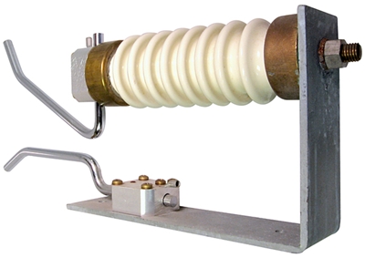
Obviously the base is grounded, and the line attaches to the top horn rod where it mounts to the end of the large insulator ceramic standoff. They can safely handle up to 50kV sustained, and over 200kV impulse. End to end they are about 20 inches (508mm) long. The distance between the shortest part of the gap is adjustable to set the approximate trigger voltage. Each leg of the balanced line uses one of these. These are very effective spark gaps since they use a principle similar to a Jacob's ladder. And ... they are very Tesla-esque!
Next, I wanted to be able to "bleed off" any static. This means coupling each leg to ground at DC and low frequency AC. The use of large fixed inductors, one for each leg, seemed to be the solution. I calculated the inductance needed to be a minimum of about 100uH for use down to 160m. However, for insurance I used two inductors with about 340uH and able to handle high current. I knew that Harris used similar devices on some of their commercial Broadcast transmitters, so this is where they came from. The inductors are wound on a phenolic coil form. They use cloth covered 10 gauge wire at 9 t.p.i The overall dimensions are about 4" x 18". One end is attached to ground and the other end paralleled; again one inductor for each leg. The two 1.5" x 2.6" ceramic insulators in the image below are what are normally used to mount these inductors. I opted for a different mounting. I modified the mounting using one normally used for vacuum variable capacitors. I mounted the inductor only on one end, the ground side. The inductor ground end is firmly attached to this mount assuring improved contact and grounding. And by removing the mount on the transmission line end reduced interaction with the transmission line, while at the same time slightly increasing the "Q" of the inductor. Here's a image of the Harris inductors I am using in its non-modified condition:
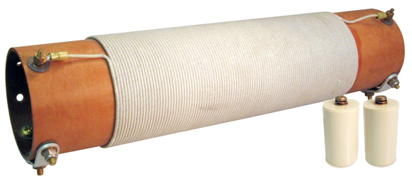
I also decided to DC block the end connected to the station side. For this I used four 20kV doorknob capacitors, two in parallel for each leg. (Right now I cannot remember the capacitance value, but I know it is in the low pf range). These block any DC impulses from traveling down the transmission line from the antenna. Did I say this is mounted on the roof of the building? It is grounded to the structure via an exposed structural I-Beam that happened to be on the roof.
The entire circuit is housed in a large 48" x 32" PVC electrical NEMA watertight enclosure. Below is a schematic representation of the arrester in question. As you can see all the components are mounted onto a machined .250" thick copper plate, which it then bonded to the aforementioned I-Beam. This is accomplished by two 4" wide solid copper straps bonded to the copper plate just below the inductors, which pass through two slots cut into the underside of the enclosure, which are then bonded to the I-Beam underneath. In the image below, a pictorial schematic, all of the various mounting hardware has been omitted for functional clarity. The drawing is not to scale, however fairly close:
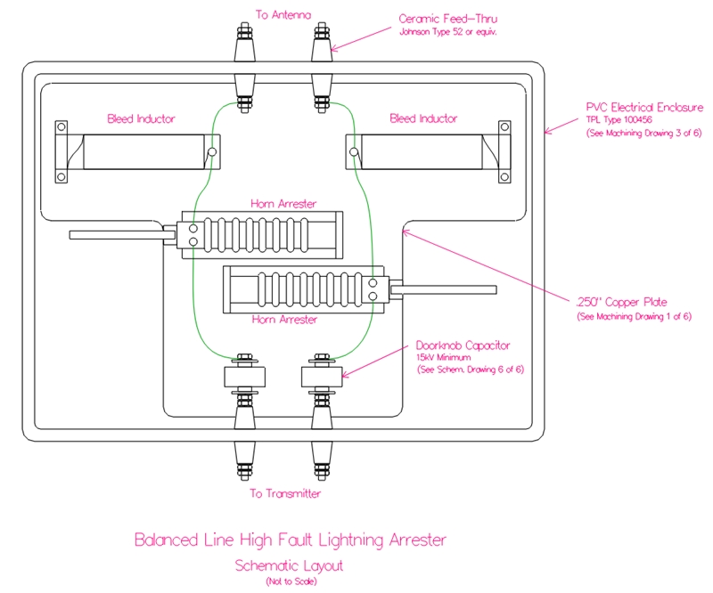
This arrester dissipates nearly all the static hash from wind, rain, snow and some atmospherics. The use of these inductors/chokes allows the horn gap devices to only act when the impulses are large. In addition to the DC blocking caps, the large discharge inductors on the antenna side are the primary neutralizing component. Any voltage development is quickly shunted to ground through the DC shorting nature of the inductor/RF choke. If large currents of a fast rising nature are presented to the arrester in such a way that a back-EMF develops across the inductor then the horn gaps arc, but the horn gaps only purpose in this regard is to collapse the magnetic field of the inductor. So noise is very low. No noisy gas discharge tubes spitting away and adding noise. This function of the horn gaps is additional to their primary use as spark gaps for near or direct lightning strikes. Those big inductors, invisible at HF, are superb for bleeding off DC and low frequency AC impulses.
This system works very well. The antenna is very quiet on receive, and it is a very large dipole antenna at 210' long, with a very long transmission line which is close to 200' in length.
At the Station Side
At the tuner side there is a smaller version of this to bleed off anything that may build up in the long transmission line. Also in case the transmission line is hit by lightning or if a strike occurs nearby, inducing a large impulse into the line. This is actually one built by Mike Koss at I.C.E. Here's an internal image of this device:
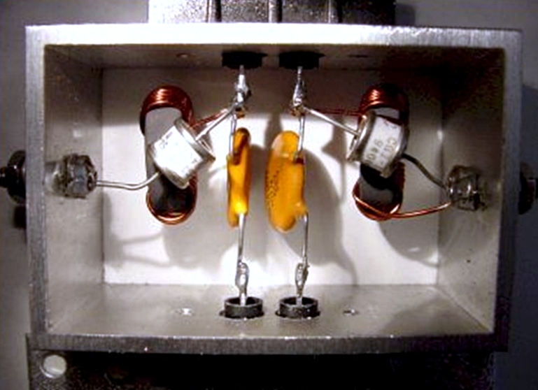
This device uses gas discharge tubes, which I removed. These devices degrade slightly over time, each time the tube fires. They also are impossible to test. So one has to make an annual routine of changing them out, working or not. Also they tend to fire off simply from static build up, causing more receiver hash in the process. Unlike in a DC shunted design (of which this device is), in an Alpha or Polyphaser the charge keeps building on the antenna wire (or in coax) and eventually discharges all at once. If you use the Alpha suppressor (or their coax switches for that matter) you may be familiar with this sound. Particularly if it is either snowing or raining. This sounds like evenly spaced pops or ticks. Like a leaky faucet. It's a Chinese water torture from your receiver! Polyphasers are not as bad since they do use a DC blocking capacitor, so while still present this is slightly reduced in their design. Here's a quote from Mike Koss from a paper he wrote on the subject:
Quote:
"Unfortunately these tiny parts have found their way to the telecommunications market and are being heralded by some lightning arrestor manufacturers as the "great savior of the world", capable of handling gargantuan amounts of current and pounding bolts of lightning into pitiful submission. How can this tiny part the size of a fingernail achieve such greatness? Well, it does not and it never did. While the tube can handle the conduction of as much as 50,000 amperes of current, it can only do so for a few billionths of a second. Actually, most 1/2 watt resistors and tiny wire scraps can do that, but unfortunately a bolt of lightning hangs around for a lot longer time - sometimes thousands of times as long."
Mike goes on to say:
Quote:
"Each time a gas tube is ignited some of it's gas is compromised. Determining the continuing current carrying capacity, attack speed, and life expectancy is difficult to measure. Simply put, it's difficult to tell what the actual condition of the gas tube is."
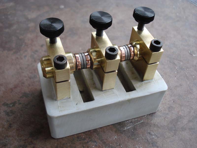
I agree, so I chose not to use these devices in my system design. A small spark gap device is being used instead. Here's is an image of that spark gap of the type I am using in place of the gas discharge tubes. It actually is from an old welding machine. As you can see it is made from brass and copper with tungsten tips and the base is ceramic. Mine is mounted on a nice wood base and sitting on top of my Johnson Kilowatt Matchbox. The tuner is sitting right near the point where the transmission line enters the shack a few inches away. The I.C.E device is right there also, attached to a copper bulkhead grounding plate bonded to the building I-Beam structure. The transmission line terminals are connected to the outside terminals and the ground is on the center. Mine is a little cleaner and of course the gaps are slightly wider than what is shown here:
I have yet to detect this device actually firing. I suspect the transmission line has been relatively safe and any major impulses at the antenna are being sufficiently suppressed by the box on the roof and by the smaller I.C.E. suppressor nearby. These smaller devices are handling only the long balanced transmission line from the roof to the tuner.
Conclusion
In conclusion, while I understand this set-up is rather extreme and not something many (if any) of you would consider for the average station build. However since this sub-forum is described as "The art and practice of building the best station that a hams money and obligations allow" I thought it would be a good article for this forum. Especially since it is extreme and different from the normal Ham fare. You can take these ideas and scale them down (or up, if that's possible) for building into your station. A well thought out suppression system for balanced transmission lines not only improves safety, it also aids in improving receive characteristics by reducing hash and induced impulse noise.
I hope this was as fun to read about as it was to write.
John, W2WDX
| Homepage / | W2WDX Station Info / | Modes / | Other Links |
| New Additions / | QSL Info / | Amateur Articles |