| Homepage / | W2WDX Station Info / | Modes / | Other Links |
| New Additions / | QSL Info / | Amateur Articles |
Since I went hot and heavy into restoring and operating vintage gear I discovered a true gem. This gem is one many of you know about, however it appears many do not understand what it is in nature and just how good it is. The Johnson Kilowatt Matchbox true balanced tuner. The purpose of this topic is to inform, to revisit this wonderful tuner which is most often dismissed by many modern Hams.
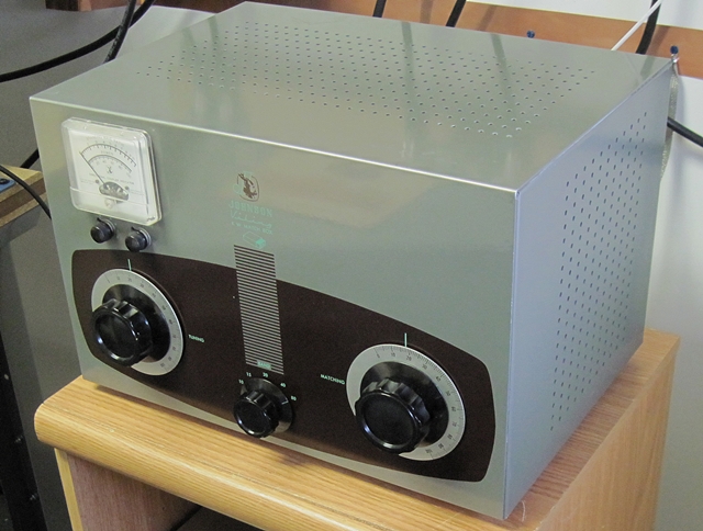
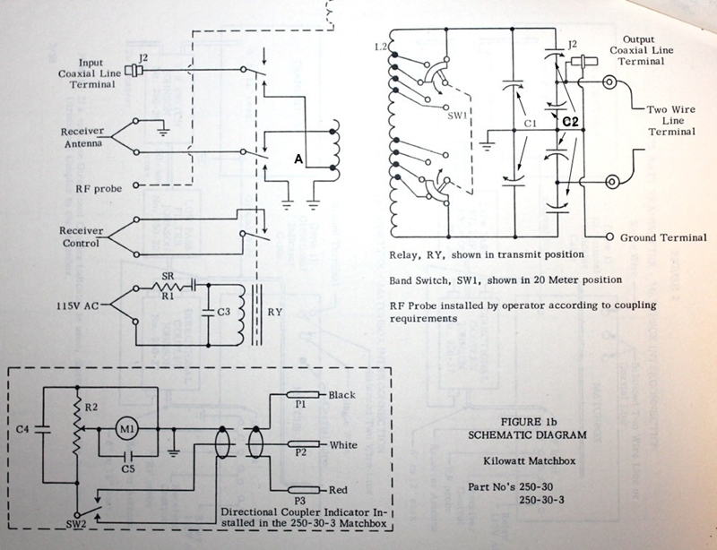
The Kilowatt Matchbox was originally designed as an accessory item for the Johnson Desk Kilowatt transmitter. The shear power of this transmitter lead Johnson to design a no holds barred tuner. Since most Hams at this time used balanced transmission line systems, it was designed for this specifically. For reference, below is a schematic of this tuner and its internal relay and connections.
The first most commonly misunderstood thing about this tuner is its power rating. The name "Kilowatt", for many modern Hams, is a misnomer. Remember this tuner was rated at a time that predates SSB popularity and the FCC change in power rating standard. Most Hams operated AM and the ratings were mostly described as an RMS input rating at a steady state carrier. Therefore the modern rating for this tuner would be 3000W PEP. In my experience this is actually a very conservative rating as well.
For the vintage operator, an UN-modified Matchbox offers features that simplify setup in terms of station control between separate transmitters and receivers. The tuner has an internal high power relay for T/R switching, and receiver muting. It uses a 115V coil which is compatible with most boatanchor T/R switching schemes. The relay also has a capacitor for release delay that slows slightly the return to receive mode. This prevents any popping in the receiver during switching. It also allows time for the magnetic fields to collapse so as to not allow residual transmit RF from entering the receiver input terminals.
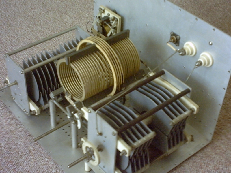
In this image you can see the internal components of an un-modified Kilowatt Matchbox. Notice the size of the components and the massive link-coupled coil. This coil is very efficient, one of the big pluses of the design. You can also see the large T/R switching relay. They are massive indeed, with the caps having sufficient spacing for I believe about 4kV.
I have heard the Johnson Matchbox described as a modified Z match. This is not quite correct. It is actually more like a link-coupled design. However, in the Johnson the link-coupled coil is fixed. The Johnson Matchbox uses a single link for all bands with no variability. This is probably its weakest feature. However, for use with most vintage transmitters it does present reasonable impedance matching to the transmitter over all but the highest HF frequencies.
The only thing I would do to improve the design is probably not mechanically feasible. This would be to have a rotary coil with contra-rotating sections (in line) to permit the full span of taps in order to eliminate the switch. The goal would be to make available the most efficient coil settings for every possible set of R+/-jX presented, but I have no idea of how to make that work mechanically and preserve the center link and main coil center efficiency. However this "limitation" is marginal and the tuner performs well in its original form factor.
The secondary coil is tapped at reasonable positions for 80/40/20/15/10 meters, shorting out the unused turns toward the outer ends. Across the outer limits of the coil is a split stator capacitor, center grounded, which is used to set the tank at resonance. The required value of capacitance will vary somewhat as the reactance and resistance at the antenna terminals is varied. Of interest to many is the fact that the split stators can be tweaked in the relationship between the two legs of the feed-line. This allows for adjustment of each leg to better create balance between each leg, effectively eliminating and imbalance due to antenna asymmetry, feed-line interaction with nearby objects, etc and therefore reducing feed line radiation.
Another often maligned issue is the sections of C2 where the two sections are connected to ground. Many have claimed this as unnecessary or overly complex. However, what these critics do not realize is how this references the two legs to ground. It serves no purpose for impedance matching, however it does serve to improve feed-line balance and reduce the potential for feed-line radiation. Most coax systems are already referenced to ground via chassis ground or shield grounding at the point where the coax enters the shack. It is a design form which is only important in terms of using balanced line; a reference to ground for a normally floating balanced line.
The terminals are not connected directly to the outer limits of the tank. Each side of ground passes to a differential capacitor. The center of each differential goes to the antenna terminal. A differential capacitor is a split stator variable arranged so that as capacitance on one side goes up, it decreases on the other. The antenna terminal on each side of ground is thus set at a certain reactance from ground and certain series reactance from the tank. This arrangement is said to form a voltage divider. It also forms a means of compensating for reactance at the antenna terminal of the tuner, allowing it to match a wide range of R+/-jX combinations that might be present at the antenna terminals and still present the requisite high impedance to the tank circuit ends. Because the entire series combination of capacitance (and capacitive reactance) appears across the tank circuit and the load, the function of the differential capacitors is not so simple as some might lead one to believe.
Also, the so-called tuning range has been (or the limits thereof) also much maligned. In my experience I find this to be a non-issue issue. It is all dependent on your antenna design. However, if you find this range is too limited for your antenna installation the addition of a little more capacitance in the form of additional doorknob caps will mitigate the large range of your particular antenna design.
Additionally, another misunderstood issue is the separate taps on the input link, one for the transmitter and another for the receiver. The input with the relay and associated circuitry includes taps for a 50-ohm transmitter connection and a 300-ohm receiver connection, since receivers continued to used balanced input strips long after transmitters had gone to shielding, pi networks, and 50-ohm outputs. I use simple TV twin-lead for connecting the Johnson tuner to the receiver. This is great for improved receiver performance for the vintage operators setup.
However be aware that many of these tuners have been modified for use with modern transceivers. Many times the relay is re-wired or bypassed. Sometimes all the relay circuits and components have been removed. A shame really. I have heard many Hams, who do not understand the circuitry describe how they hooked up the tuner to their transceiver and the tuner couldn't tune or didn't work at all showing an open circuit on the coaxial input. This is because they didn't understand the relay circuit, which is in receive mode when the relay is not powered. Some also described the tuner showing a mismatch on the transceiver since someone had previously modified and bypassed the relay improperly and connected the coaxial input to the 300ohm receiver tap of the link. You should be aware of these issue if you buy one of these and you should check the internal condition before you buy it.
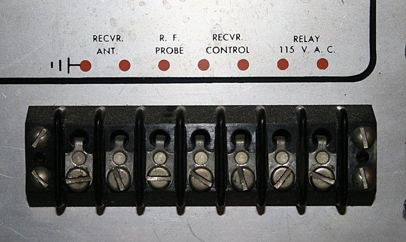
As far as the relay connections, all of the connections are found on a terminal strip located on the rear panel. This includes the transmitter switched coil voltage, the muting contact closure for the receiver, the receiver antenna connection. Also included is a terminal for the user to add a small close-coupled loop for monitoring of signals on a scope of analyzer. The nature of the loop should be designed depending on your coupling needs to whatever you are using to measure or monitor the signal. Also here is where you place the 300 ohm twin-lead for connection to your receiver 300 ohm antenna connection. Here's a close-up image of that terminal strip:
Also many of the Kilowatt tuners have built in "SWR" meters with an external directional coupler placed on the coax input for tuning ease.
There is also a smaller tuner, rated at 275watt (about a kilowatt PEP), which is almost exactly the same with smaller components. It is known simply as the Johnson Matchbox.
The Johnson Kilowatt Matchbox is a true balanced system. It differs from nearly all modern single-ended tuners in this regard. Using no toroid baluns on the output and a very efficient link-coupled coil it exhibits much lower losses when compared to single-ended modern tuners. Low loss is the overall advantage of tuners like this using balanced transmission lines. And the reduction in losses is remarkable compared to an single ended tuner using unbalanced transmission lines. In addition, its power handling ability is unsurpassed. Additionally, the proper impedance matching for older higher impenitence receiver inputs as found on older receivers is also a great feature for the boatanchor enthusiast.
For anyone interested in running vintage boatanchors from the 50's and early 60's with a balanced transmission line fed multi-band antenna would be well served to use a Johnson Kilowatt Matchbox.
John, W2WDX
| Homepage / | W2WDX Station Info / | Modes / | Other Links |
| New Additions / | QSL Info / | Amateur Articles |