| Homepage / | W2WDX Station Info / | Modes / | Other Links |
| New Additions / | QSL Info / | Amateur Articles |
Barker & Williamson 5100B Transmitter
History & Modifications
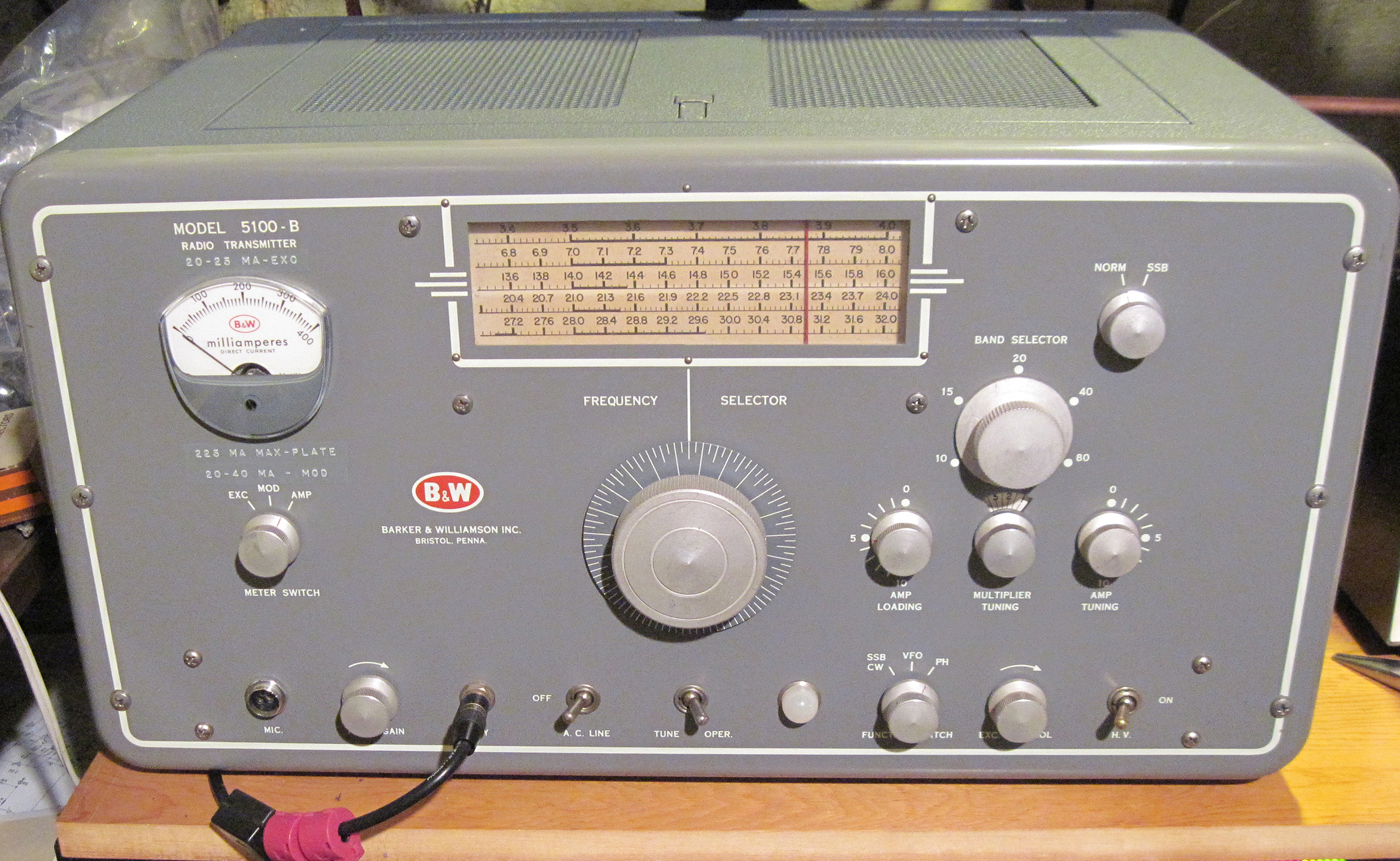
The B&W 5100B was manufactured between 1955 and 1961 by the
Barker & Williamson Company of Bristol, PA (near Philadelphia). This
transmitter offered both AM radiotelephony and CW radiotelegraphy on the
80, 40, 20, 15, 11, and 10 Meter Amateur Bands. The unit had a self
contained power supply. The 5100B is rated at 180 Watts DC power input to
the final amplifier on CW, and 140 Watts on AM, typically putting out
nearly 100w carrier. The transmitter is well known for its audio quality,
its modular design (more on that later), and its heft tipping the scales
at 85 pounds.
A separate phasing type sideband adapter was also made for this
transmitter, the 51SB-B. It is housed in a matching chassis, and the 5100B
has threaded mounting holes and cable feed-thru holes in its right side
for attaching the 51SB-B. The adapter is connected via octal type, Cinch
Jones, and several terminal strip connections. It is fully powered by the
5100B, as well as using the 5100B PA stage.
For AM operation the 5100B has a basic plate modulation
topology of a pair of 6146's in push-pull AB2 as a modulator, plate
modulating a pair of 6146's in a Class-C PA. The audio/modulator circuit
consists of a 6U8A for the mic preamp (triode section) and second stage
(pentode section), and a 6AQ5A audio driver which is coupled to the 6146
modulator tubes via a 4:1 interstage transformer. The outputs of the
modulator tubes are fed into a modulation transformer which is directly
coupled to the plates of the PA. With the exception of a Centralab
couplate which resides between the second audio stage and the driver
stage, the 5100B has none of the clampers, limiters or other audio
limiting gimmicks found in many transmitters of the
day.
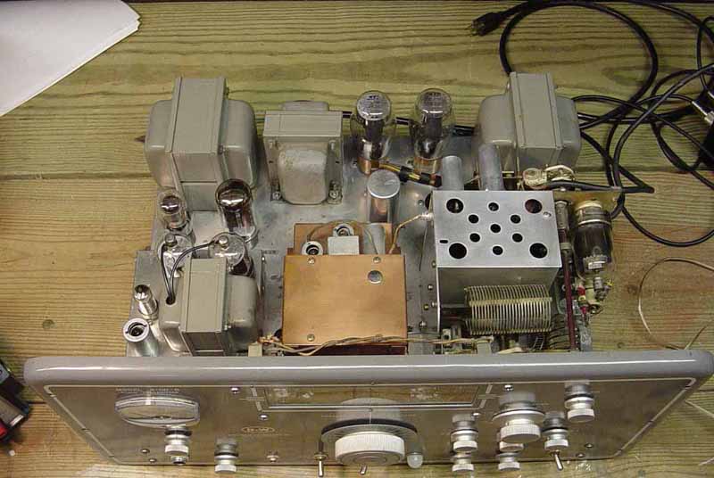
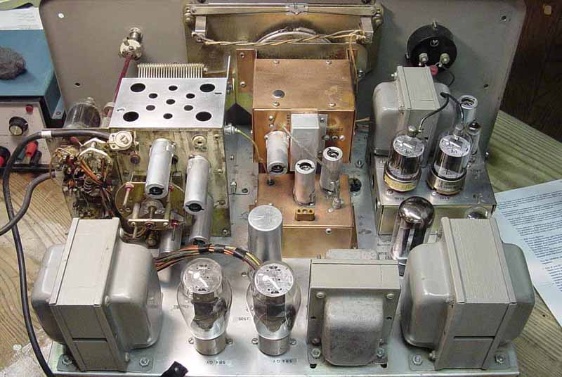
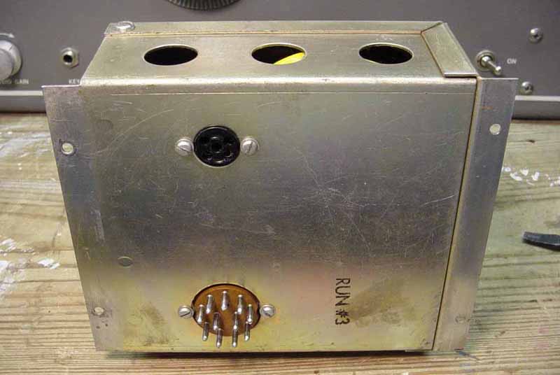
One of the nice features of this design is the modular
construction of this transmitter. The modulator, VFO, crystal buffer unit,
and the entire multiplier/RF PA unit are removable as separate complete
entities. They are connected to the chassis via various octal type and
Cinch-Jones connectors which are connected through holes in the the
chassis. Once removed, the only thing remaining on the chassis is the
power supply components and the internal wiring. The VFO comes out
complete with the housing for the circuits and the complete mechanical
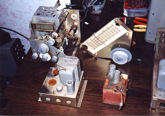
tuning knob and dial mechanisms attached. Most of these modules are
removed simply by taking out just four screws on each unit, a few more for
the VFO unit. The VFO and the Mult./PA also only require you remove the
the knobs. The shafts just pull out the front panel. No fiddling or
removing the front panel nor are there any sub-panels here. The shafts are
not attached to it. They have there own mechanical support built into the
respective module itself. For instance, if you make the proper cabling, it
allows you to remove the modulator, plug in the cable and work on the
modulator on the table in front of your transmitter and test the circuits
while it is connected and running attached to the transmitter in
situ.
This article details some modifications that can be performed
to improve the overall audio quality. Near broadcast quality audio
can be had after these mods are performed. There is a PDF document with a
schematic documenting all of the mods mentioned here. This schematic is
not a complete schematic of the entire transmitter and only includes the
circuits within the scope of this article. However the circuits are shown
contiguous, and not just chopped up into isolated segments.
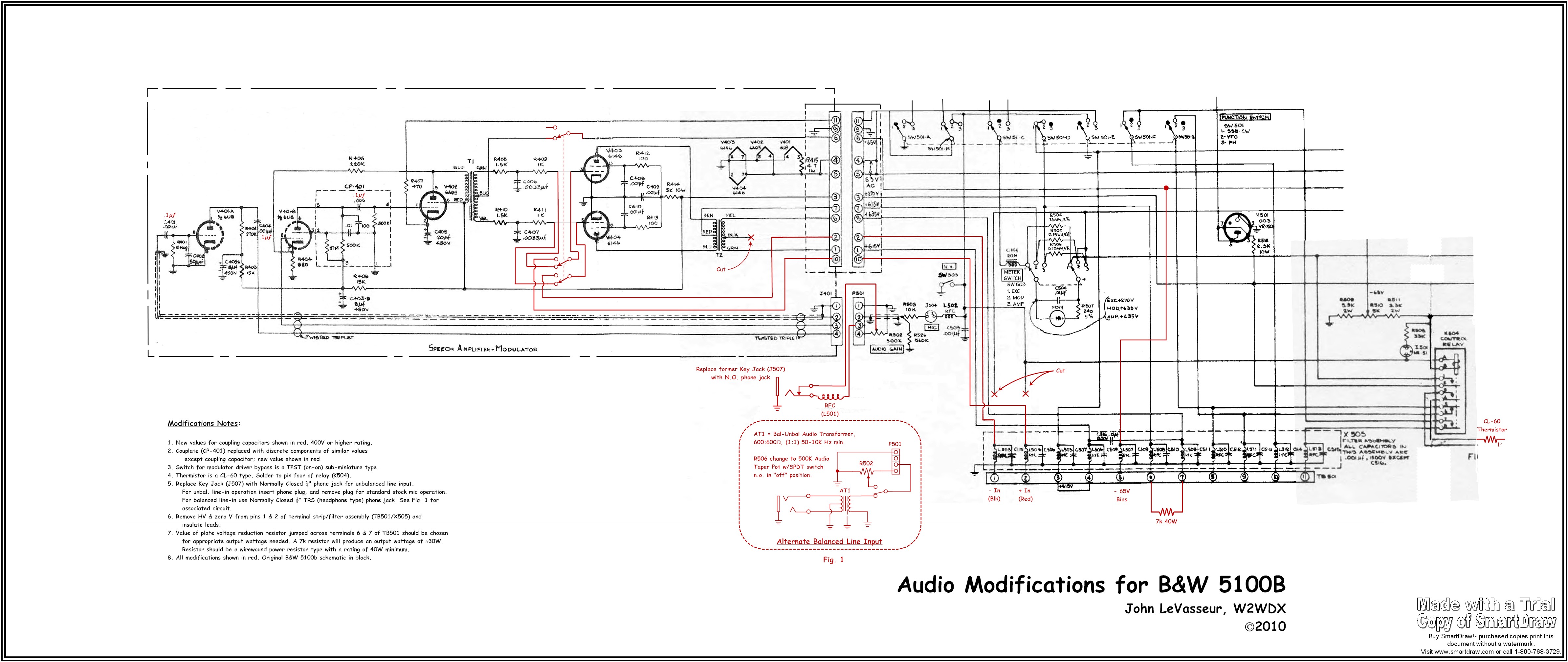
Here's a link to this schematic:
http://www.qsl.net/w2wdx/images/Mods.pdf
A high
resolution JPG of this is available here (huge file warning!):
http://www.qsl.net/w2wdx/images/Mods.jpg
A full
schematic & users manual for the B&W 5100B can be found at the
BAMA site. Here's a link to that document:
http://bama.edebris.com/download/b&w/5100b/5100b.djvu
You
will need a program (DJView) to view the manual file. Download it at: http://windjview.sourceforge.net/
Some Simple Audio Mods
Changing the values of the coupling capacitors in the audio chain
to .1µ, replacing the stock .001µ caps, is enough to fatten up the audio
quality significantly. Also replacing the couplate with discrete
components and changing the coupling cap to .1µ as well is highly
recommended.
Another slick trick involves some more involved modification. This
one does sacrifice the Key input in favor of using it for a line level
input. It involves simply disconnecting the RF choke following the key
jack input, replacing the Audio Gain pot with a similar value pot that has
a SPST switch attached to the back. The wire that came from the mic amp
stage to the pot is placed on one side of this switch and the other side
of this switch is wired to the end of the pot where this was previously.
The RF choke coming off the former key jack is then wired to the wiper of
the pot. In this configuration all you have to do is turn the audio gain
to zero or in this case "OFF", and the switch disconnects the mic preamp
from the rest of the circuit. Plug in your line level audio chain and
adjust the audio level using your outboard audio gear, preferably
monitoring on a scope. If you want to simplify this you can simply replace
the Key jack with a ¼" phone jack that has a normally closed contact and
keep the stock gain pot. The contact disconnects the internal mic preamp
when a plug is inserted. Remove the plug for stock microphone operation.
(Note: This is the mod shown on the mod. schematic).
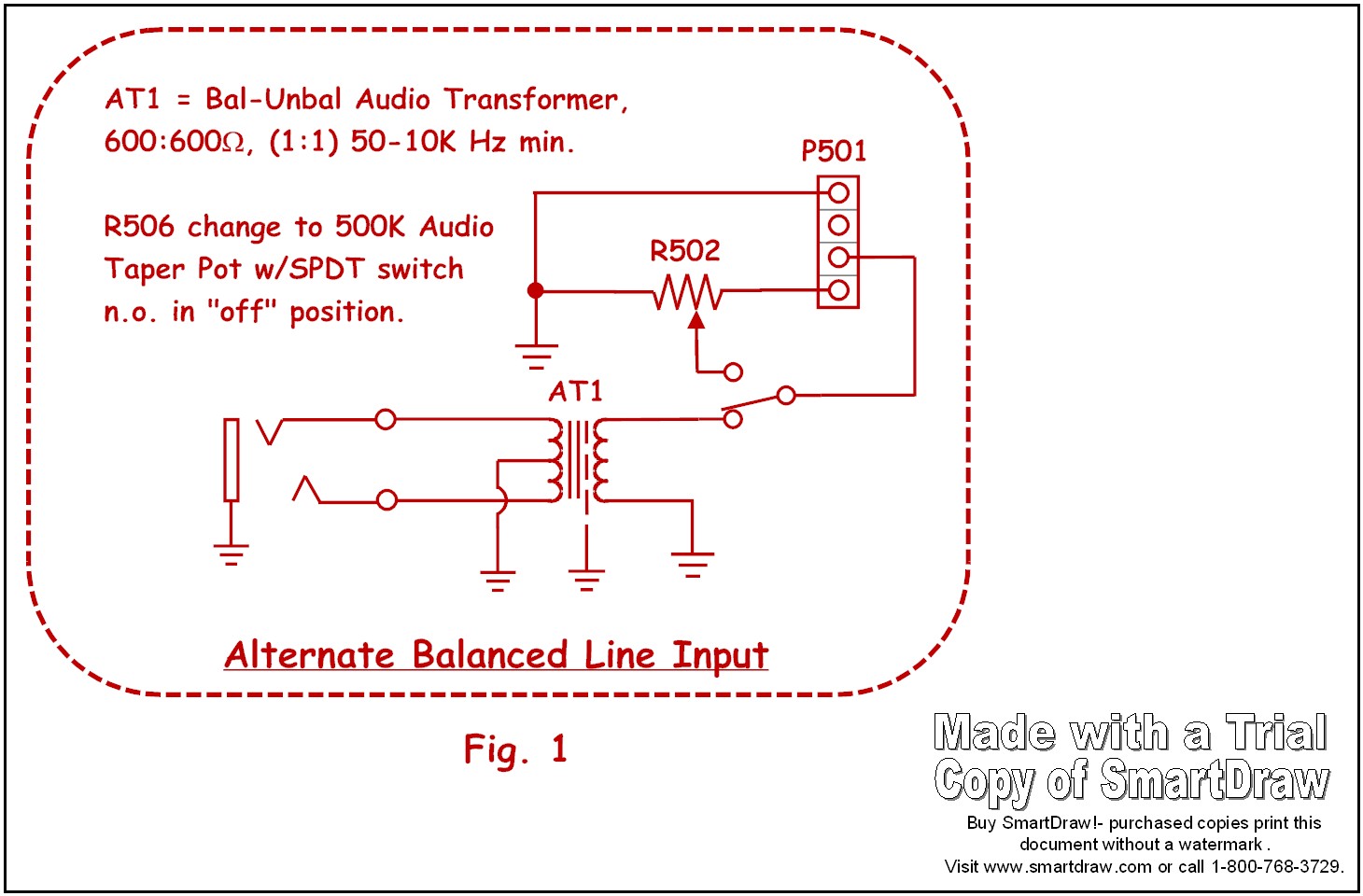
If you want to
take this a step further, you can change the phone jack to one that is TRS
(tip-ring-sleeve). Wire in a small 1:1 600O audio transformer that
converts balanced to unbalanced. Wire the ungrounded side of the
unbalanced output of the transformer to the pot switch contact and the RF
choke (which leads to the wiper of the pot) to the other side. Wire the
common to pin 3 of P501. See Fig.1 (The pot switch in this case must be a
SPDT type). This allows you to drive the radio with a balanced line level
signal when you turn the gain knob to the full "off" position. In the "on"
position this switches the input to the internal radio audio driver chain
with the pot controlling level from the stock mic input as usual.
One note: While Radio Shack offers a 1:1 transformer of this type,
its frequency response is quite limited and may defeat the purposes of
these particular mods, that being broadening the audio frequency response
of this modulator. There are much better transformers, which are very tiny
in size offered on the web. Jensen makes several (what I used was a Jensen
JT-11SSP-6M), but these can be pricey for the more frugal HAM's. The
Jensen I used is sever overkill but I had one from my audio profession I
wasn't using, so I used it here. Many small high quality transformers
which are much less expensive are available. Check online.
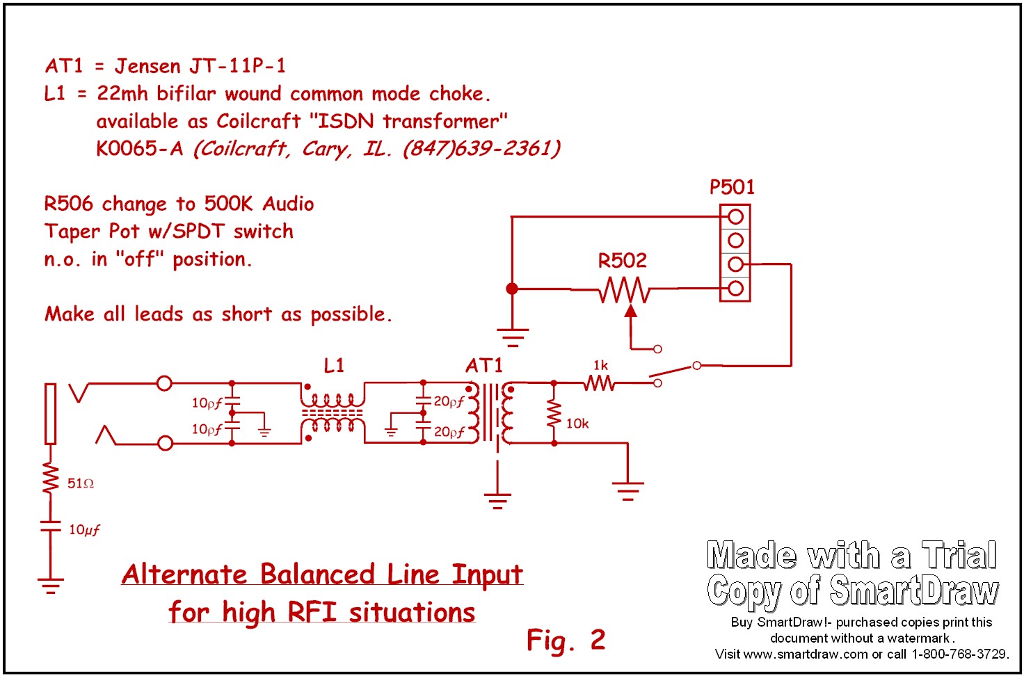
If you
have an RFI problem or just want to prevent the potential of one, you
could try this circuit. (See Fig 2) This circuit also has some additional
changes that might better match the input of the 6U8 which could be
incorporated into the original alternate circuit. Values may change if
other transformer are used other than the Jensen & Coilcraft
types.
These mods allow you have the original microphone input (for
your beloved D104) with the gain control and have a line level
input without changing the appearance or function of the radio one iota!
(except for the front Key input).
Modulator
Modifications
Some more sophisticated
modifications of the modulator can be performed that can improve overall
sound quality of the transmitted signal. Some of these that I have
performed involve very minor drilling and installation of items like
internal switches & connectors.
The suggestion was made to me
one evening on the air by Jeff, W2NBC to connect an external drive stage
directly to the grids of the 6146 modulator tubes. (Hmmm) This is the
classic audio amplifier connected to a flipped around hi-fi audio output
transformer to drive the grids. The method I used was specific to the
audio gear I had available and other methods and gear can certainly be
applied here. I had an old Dynaco ST-70 tube audio amplifier. One of the
nice features of this old vintage amplifier is the use of very high
fidelity output transformers. Also, the amplifier would have more than
enough power output to drive the grids of the 6146's and maintain a high
level of headroom in the driving audio amplifier. This amplifier uses two
EL-34's in P-P.
I disassembled the ST-70 and removed one of the
output transformers. Basically, I removed the entire "left" channel and
all of its components, leaving it as a "monoblock". After cleaning up the
chassis, repainting the transformers, and otherwise making it all nice and
pretty, I rewired the amplifier and set the bias. I checked the amplifier
for performance.
I took the removed output transformer and mounted
it on one of those Hammond cast-aluminum project boxes, added two pair of
five-way binding posts and a ceramic feedthru connector for the bias
voltage for the 6146's. I wired the 8O secondary to one set of binding
posts and the primary to the other binding posts next to the feedthru
connector. Across the binding posts connected to the 8O secondary I
soldered an 8O/50w resistor. For the mod that follows, any low power audio
amplifier can be used. Output power of the amplifier should be between 8
to 25W. Any hi-fi P-P type audio output transformer can be used, flipped
around and loaded with an 8O power resistor.
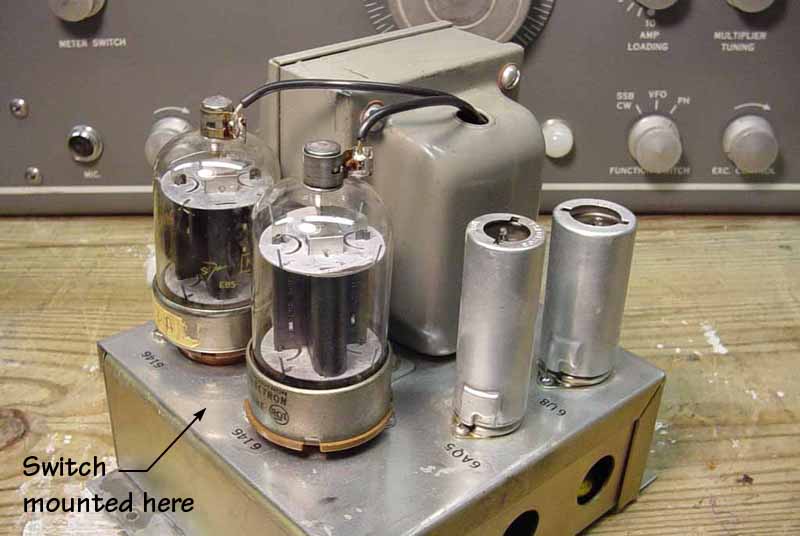
Now comes the mods to
the 5100B that involve the drilling. (Don't fret ... it's just one tiny
hole on the modulator sub-chassis). On the modulator module between the
modulator tubes and near the edge of the chassis, drill an appropriate
hole and mount a sub-miniature TPST switch. This switch disconnects all of
the radio's circuitry before the grids of the 6146's and connects the
grids and the bias voltage directly to several unused pins on the 11 pin
plug (P401) that connects the modulator to the radio chassis
circuitry.
In the modulator, on P401 remove the black wire on pin 2. This
is a terciary output lead from the mod transformer that is not used for
normal operation of the transmitter (except when used with the 51SB-B SSB
Adapter ... I think, not sure). Insulate it well and leave it. Remove the
ground connection from pin 10. (Don't worrry, there is already another
ground connection on pin 9 and this connector can handle the current with
just one ground pin. Besides the chassis is at the same potential, and
these pins only come into play when you have the modulator module removed
from the chassis). The lead connecting the grid switch of V403 goes to pin
2. The lead connecting the grid switch of V404 goes to pin 10. These are
used to connect the switch which controls the grid input switching to the
terminal board on the rear of the chassis.
On the main chassis,
several terminals on the terminal board (TB501 Term. 1,2 & 5) are
utilized to feed the signals from the external source to the modulator
grids via its large multipin plug on the bottom of the modulator
sub-chassis. To do this remove the HV wire from terminal 1 and the zero
volt wire from terminal 2 and insulate them well and just leave them. Then
move the wire from terminal 5 and move it to terminal 1. Also locate
the -65v negative bias voltage and wire that to terminal five. You may
want to take it from the J503 connector or the wiper of R510 (Mod Bias
Adjustment) mounted on the chassis near the PA section. Disconnect
the ground lead from pin 10 of the 11 pin jack (J503) and run a wire to
TB501 terminal 2. The wire you moved from terminal 5 to terminal 1 on
TB501, connects the other switched grid lead.
Now connect the
positive lead of the flipped output transformer to terminal 2 and negative
to terminal 1 and connect the center tap of the transformer (the ceramic
feedthru connector) to terminal 5 on TB501 for the bias. Fire up the
transmitter and run up your audio amplifier. Using a scope, monitor your
transmitted output waveform for 100% modulation.
Refer to the
schematic provided here to clarify the connections.
The Simple "Turbo"
Mod
While the pair of 6146's in the PA can
produce a 90-100W carrier output on this transmitter, you may want
punch that up by using an external linear amplifier. Unfortunately,
most commercially built amplifiers will be toast quite quickly if you
drive it with that carrier level. Not to mention you will have no headroom
left on top of the modulation peaks, if you have any.
To reduce the
carrier output on this transmitter, a very simple and effective "mod" can
be performed. Simply remove the jumper connecting terminals 6 & 7 on
TB501. This an external access point for the plate voltage which goes to
the modulation transformer. I should point out here, the voltage across
these terminals is 635V and can really smart (or even kill) if you are not
careful. Across these terminals place a power resistor between 7k &
20k (depending on the amount of output you need to drive your amplifier).
I used the type that has the screw terminals on it and mounted just above
the terminal strip on the back of the chassis on the perforated grill. I
used two ceramic standoffs to mount the resistor, and uses high voltage
wire down to the terminals. The resistor should be rated at 40W minimum.
No change to screen voltages or any other modifications seems to be
necessary, as far as I have observed.
That's all there is to it.
Works well!
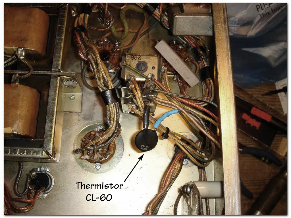
The Simple Soft-Start
A
nice mod that limits the inrush current when turning on the B+ (and to get
rid of those loud "ka-chunks" that could at times shake the entire cabinet
of the 5100B) is adding a thermistor in series with pin 4 on the Control
Relay (X504). A CL-60 type thermistor is a good choice. The time constants
and current rating is perfect for this transmitter. It is rated at 5 amps
steady state current, 10 ohms cold resistance and about 0.2 ohms when hot.
These get very hot, so take care where mounting it!
This mod came
from Mark Bell, K3MSB.
Replacing the Selenium
Rectifier
There is a selenium rectifier (SR501)
used on the negative bias voltage supply. These are prone to failure and
should be replaced. Remove the selenium rectifier from the ceramic
standoff it is mounted on. Screw a terminal strip with multiple lugs onto
this standoff. Watching the polarity, use a 1N4007 diode to replace the
selenium. In order to match the voltage drop of the selenium rectifier,
place a resistor in series after the 1N4007 to achieve the correct
voltage. You should do this by trial and error until you achieve the
correct voltage of -140V on the negative side of the 40µ/150V filter
capacitor (C519) that follows the diode.
Some Things to Check When When You Get Your
5100B
Since this transmitter is now over 50 years
old, you should of course change all the electrolytic capacitors. Most are
contained on/in the main chassis, and two more are found in the modulator
module. Use high quality NEW (not NOS) capacitors. The FP can type
electrolytic (C520), which is a 40/40/40µ @450V, is still available if
you want to "keep it original". CE Electronics is still manufacturing this
can new, using Mallory's original equipment. But they are not cheap,
costing around $34USD at retail pricing. It can be purchased online from
Antique Electronic Supply (www.tubesandmore.com). I only suggest them since they
usually have this can in stock all the time (as of the time of this
writing). Of course you can simply use ordinary axial lead caps underneath
to save money. Whatever type you choose, do this first.
I stayed
with the stock values of capacitance. On the bias supply I recommend
raising the voltage rating from 150V up to 450V on these capacitors, since
the first filter cap in that supply is very close to the normal operating
voltage of -140V. I have found the amount of capacitance in the stock
design is more than sufficient, and the stock supply is fairly stiff as
is. No hum or ripple was detected anywhere in the circuitry. The oil
capacitors in this transmitter (one used across the HV choke & two
feed-thru filter caps on the AC input), most likely do not have to
replaced. But it is advisable to check them for leakage, as a rule of
thumb.
One other suggestion I would like to make, is on the
resistors (R520 & R521) used across the HV filter capacitors. While
the original design uses 68K, 2W, 10% carbon composition resistors,
I went with hand matched 2W, 5% Metal Oxide Power Resistors instead. Even
distribution across these capacitors allows the filtering to work better,
so the closer tolerance coupled with the better long-term reliability of
these types of resistors seemed like a good choice. It is a minor thing
and not important or even necessary, its is just small detail I felt could
be addressed.
While you're in there, you should also check the
values on the various carbon composition resistors. They do change value
over time and should be checked. Replace any you find out of
value.
The 5100B uses two continuous bead chains to drive the
mechanical of the multiplier. These can stretch over time, causing the
chains to slip. There is an "idler" wheel on each that can be adjusted to
take up slack. Do not make the adjustment too tight. And whatever you do,
don't break those bead chains! They are the rarest & most difficult to
find components in this transmitter. They are made from pure unobtainium!
If the multiplier tuning control works smoothly, it's best not to mess
with these chains.
If you find you cannot reach 100% modulation you
should check the 4.7O/1W filament dropping resistor (R415) for the 6U8
(V401) inside the modulator. Its value can and does change over time in
this transmitter and it will reduce the modulators ability to achieve full
modulation.
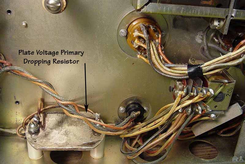
You may get a scare the first time you tune your "new"
5100B when smoke appears near the modulator the first time you switch it
into tune mode. Inside is a very unique plate voltage primary dropping
resistor (R525 "Special Resistor"). It is comprised of a disc of mica
wrapped with about 20 turns of Nichrome wire, which is then sandwiched
between two more discs of mica. It is mounted to two ceramic standoffs.
Sometimes if the transmitter hasn't been used for a while dust and stuff
may build up inside or on this resistor and burn off when the transmitter
is first tuned. If you find this resistor is not functioning, it cannot be
found. It has to be made. I bought sheets of mica & nichrome wire, and
using an x-acto knife and alot of patience, made a new one that functions
and looks exactly like the original. I used the original as a guide for
cutting the mica sheets. I made two, just to have spare. If I can do it, I
assure you it can be done by anyone. Since it's not mentioned in the
schematic or manual, the value of the resistor is 27O at probably about
50W. Any power resistors near these values can be used, of course. The
circuit seems to draw about 30-35W while used.
... And In Conclusion
The
B&W 5100B is a great transmitter; a true classic! Hopefully some of
these modifications will allow you to enjoy it more without having to tear
it apart. The performance will be increased and it will remain virtually
original.
73
John LeVasseur, W2WDX
[email protected]
P.S. - I
would like to thank Mark S. Bell, K3MSB for his assistance and knowledge
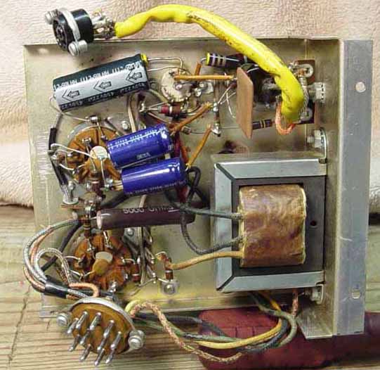
of this transmitter, and his subsequent contribution to this paper. (www.k3msb.com). The
images used here are of his 5100B and as soon as I get a working digital
camera I will put up images showing my mods in detail.
Also, I am
sure that there are some technical flaws in my modifications, due to my
limited experience at the time of this writing. While they may work fine
for me, I of course may be unaware of a better approach. That being said,
any suggestions for improvements and/or corrections are encouraged and
appreciated!
| Homepage / | W2WDX Station Info / | Modes / | Other Links |
| New Additions / | QSL Info / | Amateur Articles |