This is the basic schematic of the preamplifier and tone control circuit that I built and installed in the base of my Astatic D-104 microphone. For more details, you can watch this video that I put together that discusses this design and shows the performance of it using a signal generator and oscilloscope.
The first stage is a simple gain stage, with some high-frequency roll-off. It is loosely based on the single stage opamp-based D-104 preamp that appeared in QST in August 1999.
The second stage is based upon a widely published, active base/treble boost/cut circuit. In my implementation, the two pots (for bass and treble control) are trimpots. They are set before burying the circuit into the base of the D104.
Strategic placement of capacitors, ferrites, etc. would likely be necessary to fully RF-proof the preamp. The schematic shows the power being obtained from the rig. Since the preamp draws such little current, I decided to shunt regulate the preamp to provide a constant load to the 8V supply and help isolate any potental RF.
The opamp shown in the schematic was picked mainly due to its low power and availability (in my parts bin!). The circuit will use any decent single supply opamp. A TL072 would be a good choice, as well as probably dozens of others.
Many have asked... I am sorry, I don't have a printed circuit board (yet), nor do I build these for profit. This information is being provided for the general use by the amateur community. If you want to check out a similar EQ (and I consider a better design), check out Bob ND2M's design. He offers a CD with all construction information and enclosure decals, and PCBs are available through Far Circuits.
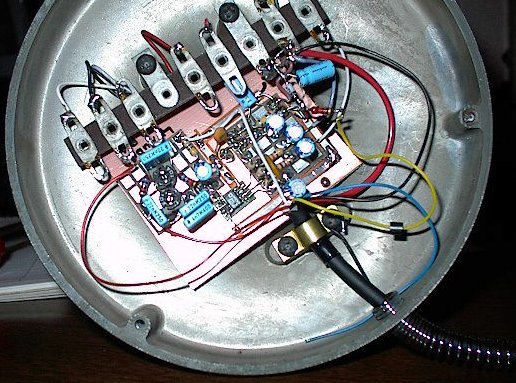
Well, I've now built a second one into another old D-104. This one is powered directly from my TS-870S and is mounted inside the base of the mic. A couple of values have been changed slightly. I only had 22nF caps available, so the three 15nF caps are replaced with 22nF, the 10K resistors on the bass side are now 6.8K, and 4.7nF is shunting the treble wiper to the right end of the pot to control/limit high frequency gain. I used a 4.9V shunt regulator off of the rig's 8V supply to run the preamp. A picture is included below.
The response of this circuit can be adjusted basically between
the limits shown in the plot below:
By the way, this is the schematic of the stock D-104 preamp...