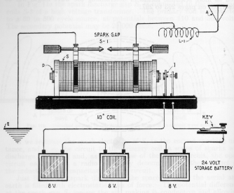
AMATEUR RADIO

A Brief HISTORY

SPARK - GAP

by w1fji

The first thing I want to stress is that "SAFETY WAS NOT A MAJOR CONCERN" during the days of Spark, some of the methods used were VERY DANGEROUS. Now that I have said that, let me move on. There was a certain amount of excitement that was assoicated with Spark Gap transmitters. Without getting into the theory or design of these Spark Gap Wireless transmitters, let me attempt to give you an over-view of their operaton.

In their simplest form, some of the early models' of the wireless transmitters were designed by Guglielmo Marconi a young Italian inventor. By the age of 21 he had studied many of the experements of Maxwell and Hertz, and was convinced that it was possible to transmit signals by electromagnetic waves. After having performed many of the experements himself, Marconi had proven that it was indeed possible to communicate by electromagnetic waves. Some of his early wireless transmitters were powered by either low voltage storage batteries, or a D.C. dyamotor which would produce 5 to 30 volts D.C. The low voltage was fed to one side of a telegraph key. As the telegraph key was depressed, and the circuit closed, current would flow into the primary side of an induction coil. This would induce high voltage currents to flow in the secondary windings of the coil.


These high currents would charge the antenna, then discharge across the sprak gap electrodes to ground. This action would produce magnetic waves for each discharge across the Spark Gap electrodes. The antenna was connected to the induction coil by means of another coil with a moveable tap. A broad band wave would then be radiated from the antenna.

Another of the Marconi designs employed a low voltage A.C. source. This low voltage A.C. was fed to the primary side of a transformer. When the telegraph key was depressed, this induced high voltage currents to flow in the secondary windings of the transformer. The high voltage alternating currents at the secondary of the transformer could range from 2000 volts to 25,000 volts A.C. These secondary high voltage currents were then fed into a tuned circuit, which is inductively coupled to the antenna. The alternating currents in the secondary would alternate back and forth within closed oscillator circuit, which was made up of a coil, high voltage condenser an spark gap electrodes. The high voltage currents would first charge and then discharge at a frequency twice that of the source voltage across the gap electrodes. Next the currents were induced into the antenna through a transformer and then radiated.


Other designs would employ a Rotary Spark Gap, also known as a multiple spark system, which was motor driven. On the shaft side of the rotary would be a rotating arm with two electrods 180 degs apart which would rotate like a wheel. Around the outside of the two rotating electrodes were several fixed electrodes. As the rotary spun, and the telegraph key was depressed, the high vlotage currents would discharge across the gaps of the rotary. With each make and break of the heavy copper contacts on the telegraph key, sparks would jump the gap of the electrodes. The rest of the circuit would be somewhat the same as I have discuss above. As you can imagin, the contacts of the telegraph key needed to be able to handle 16 to 18 amps. Not only did the telegraph key have to employ heavy contacts, but the electrode gap contacts themselves would heat up due to the discharging of the stored emergy. The rotary that I have, uses heavy copper blocks on both the rotary wheel, and for the two stationary contacts. I can recall a visit to a Steam and Wireless Museum somewhere in South Rhode Island where they had a working Spark Gap Transmitter. I can remember the sounds that were made not only from the rotary but likewise the sparks that produced when the telegraph key was depressed, it was quite a sight.

The sounds of the rotary turning and the sparks jumping the air gaps could be heard all over. In the early days of Amateur Radio these were common sounds. The emergy generated by this method was very powerful and obviously dangerous. These were the days when hams, were expermenting with various ways of generating a wave, various antenna configurations, and receiving apparatus possible. The actual signal produced by this method was very crude sounding as these waves were produced by alternating currents.

Large coils had to be hand wound for use as transformers, oscollator and antenna coils. Large knive switches were used to switch not only the power, but were also used to switch the antenna from the spark gap to the receiving apparatus, as well as antenna to ground. The greatest distance they were able to transmit was about 100 miles. Some might remember pancake transmitter inductances and loose couplers that made up important parts in the then moderm station. A typical station in 1916 might enclude a 1/2 kw transformer that supplied 14,000 volts, an eight section condenser and a Hy-Tone rotary gap. The receiver, or Audion was used for reception with Crystaloi and Perikon detectors which served for most of the work. Completing the Ham station might be a six wire antenna 70 ft high. Although I have been calling this device an antenna, it was also known as an aerial.

Radio communications had come a long way from the early on experements of Hertz, Maxwell, Marconi and others. Although the Spark days were quite unique, Amateur Radio was moving forward. Like everything else, Spark was destin to give way to the next phase of Amateur Radio. For some, the move to the next phase would be an easy one. While for others the change from Spark would not come so easy. The American Radio Relay League was founded by Hiram Percy Maxim and Clarence D. Tuska around June or July 1914. Amateur Radio was growing and it was now time for the hobby to move out and make its' mark in the world. Somewhere around 1920 through 1922 Spark was on its' out, and Amateur Radio was begining a new era.

There are many articles on Maxwell, Hertz, Marconi and others who have contributed. I would suggest that you visit your local library and read up on some of the very interesting experements they had performed. Even today Amateur Radio is undergoing many changes. I have seen the change from CW and AM to SSB and DSB, from SSB, DIGITAL, DSP, CODE / NO CODE, AMATEUR SATELLITES and now to Ham Radio on the INTERNET. Amateur Radio has always been associated with each of the changes in communications. Where do we go from here, your guess is as good as mine. Where-ever it is, you can bet that Amateur Radio (HAMS) will be there.

Photo of 1915 Spark Station in New Bedford, Mass.


CW vs SPARK

King Spark !
grown now to full maturity, developed and prefected by years of pre-war
and war experience, it reached its highest peak in the succeeding eighteen
months. Glorious old sparks! Night after night they boomed and echoed down
the air lanes. Night after night the mighty chorus swelled , by ones, by twos,
by dozens, until the crescendo thunder of their Stentor bellows shook and 
jarred the very Universe! A thousdad voices clamored for attention.Five-
hundred-cycle's high metallic ring. The resonant organ basso of th sixty-cycle
"sync". The hash resounding snarl of the straight rotary.

Character: Nevous, impatient sparks, hurring petulantly. Clean-cut busin-ness
like sparks battingsteadily along at a thirty-word clip. Good-natured sparks 
that drawled lazily and ended in a throaty chuckle as the gap coasted
down-hill for the sign-off.

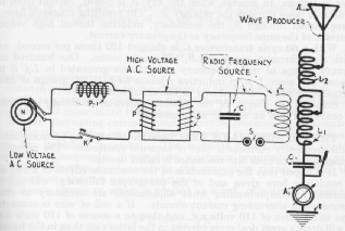
Survival of the fittest. Higher and higher powers were the order of the day.
The race wason, and devil take the hindmost.
Interference.
Lord, what interference!
Bedlam!
Well, it could not be Utopia.
                    -Arthur Lyle Budlong, in
                      The Story of the American Radio Relay League
73s' de w1fji

Return to Home