SERVICE SHEET D
Description
A9, Peak, Deviation and Rang Switch Assembly
A9 REMOVAL AND DISASSEMBLY PRODECURE
Set Peak Deviation and Range switches fully ccw.
Not critical they can syncronized later.
Remove Peak Deviaion and Range switch knobs. The knobs are secured with allen screws in the knobs.
The .050" (range switch) especially can be problematic. If really and truly siezed a 1/16" carbide will do the job. Unfortunatly I know this for a fact.
Place instrument upside down and remove bottom cover (see Service Sheet G).
Sheet G is going to tell you to remove the cover same way as any HP of this form factor. Remove the 4 Pozidrive screws, slide the cover back about 1/2" and lift from the rear.
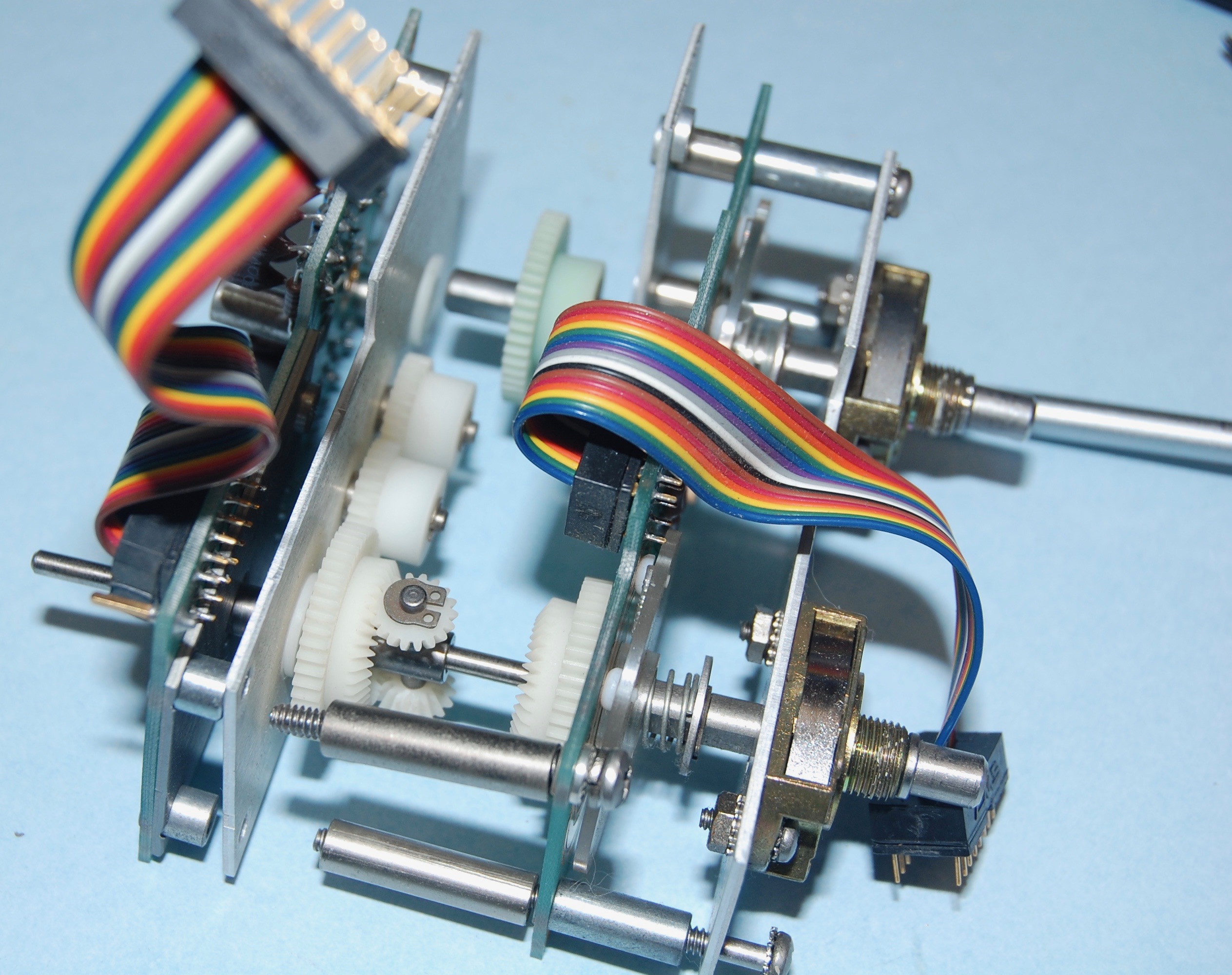
Click for the full size picture. It's set to open in a new window or tab. Take a moment to orient for what's coming. The A9 assembly is centered and consists of the two rotory shafts (range and deviation), gear drive, the A1 board (front) A2 board (rear) and two ribbon cables which are hard wired to the A1 and A2 and plugged into the A13 board underneath. The range shaft is coupled to the A10 attenuator via a white plastic coupler.
Remove two nuts hat secure A9 Assembly to front panel (located at switch bushings). 7/16"
Remove connectors A9A1P1 and A9A2P1 from jacks on A13 Assembly. Lift rear of A9 Assembly until coupler slides on apart. Gently slide the assembly back and up to remove. Re-install assembly by setting both switch shafts fully ccw and reversing the procedures in steps one throught six. If Options 003 is installed, remove both cables from the Reverse Power Assembly.
Before removing the connectors check the orientation, just in case. Note the diagonal at the pin 1 corner. Lifting at the rear is going to let the white coupler slots slide out of engagement with one of the (hopefully) vertical edges. The A10 assembly also had detents and can be set correctly for assembly. Option 003 is the reverse power module visible on top of the A10. It's not at all clear that the cables from the Reverse Power Assembly need any action.

NOTE
The detents of both A9 Assembly and A10 Assembly switches must align and correspond to the same positions. Check that the actual RF output frequency agrees with the counter indication on all ranges. (Refer to paragraph 5-29.)

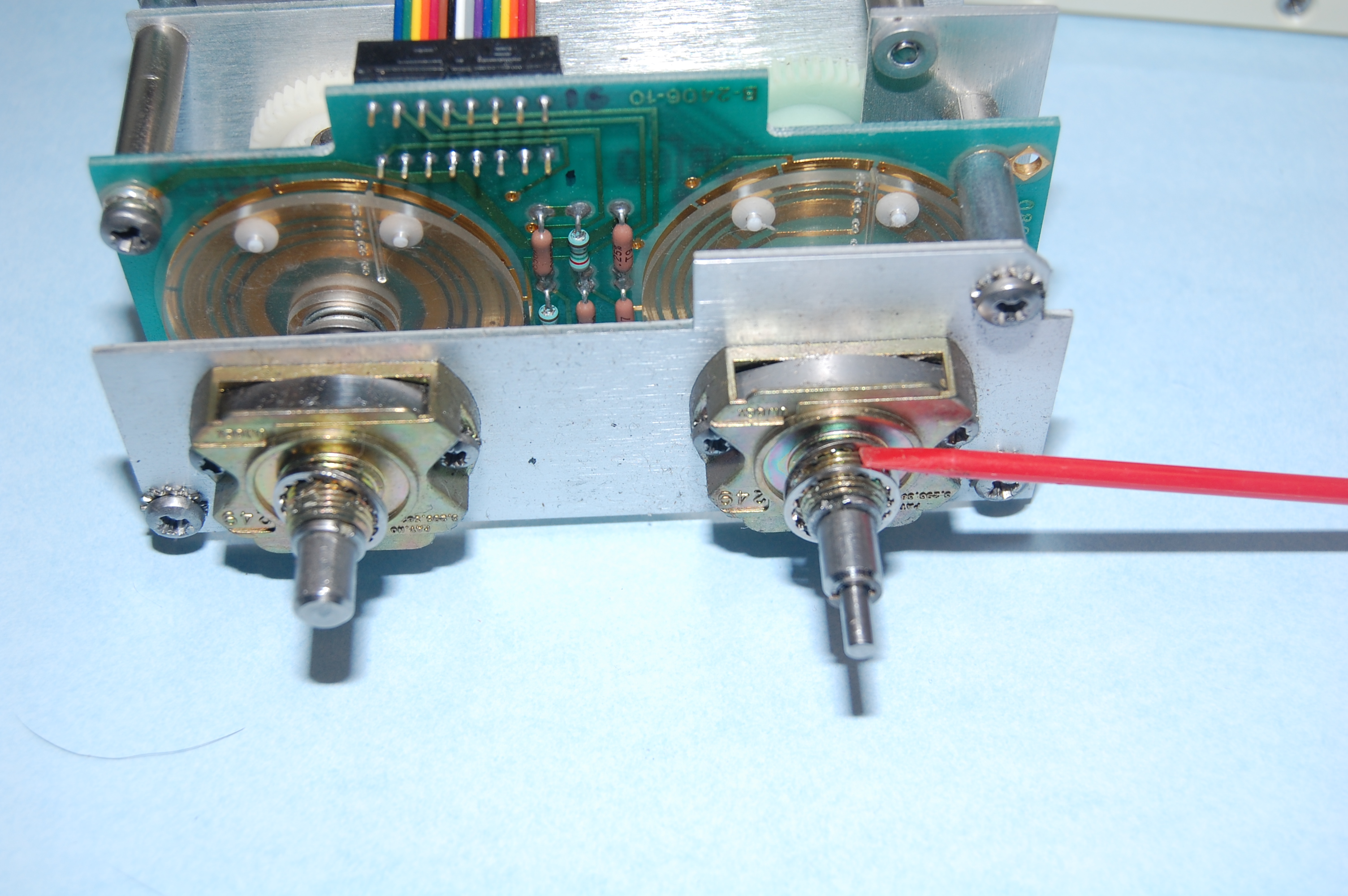
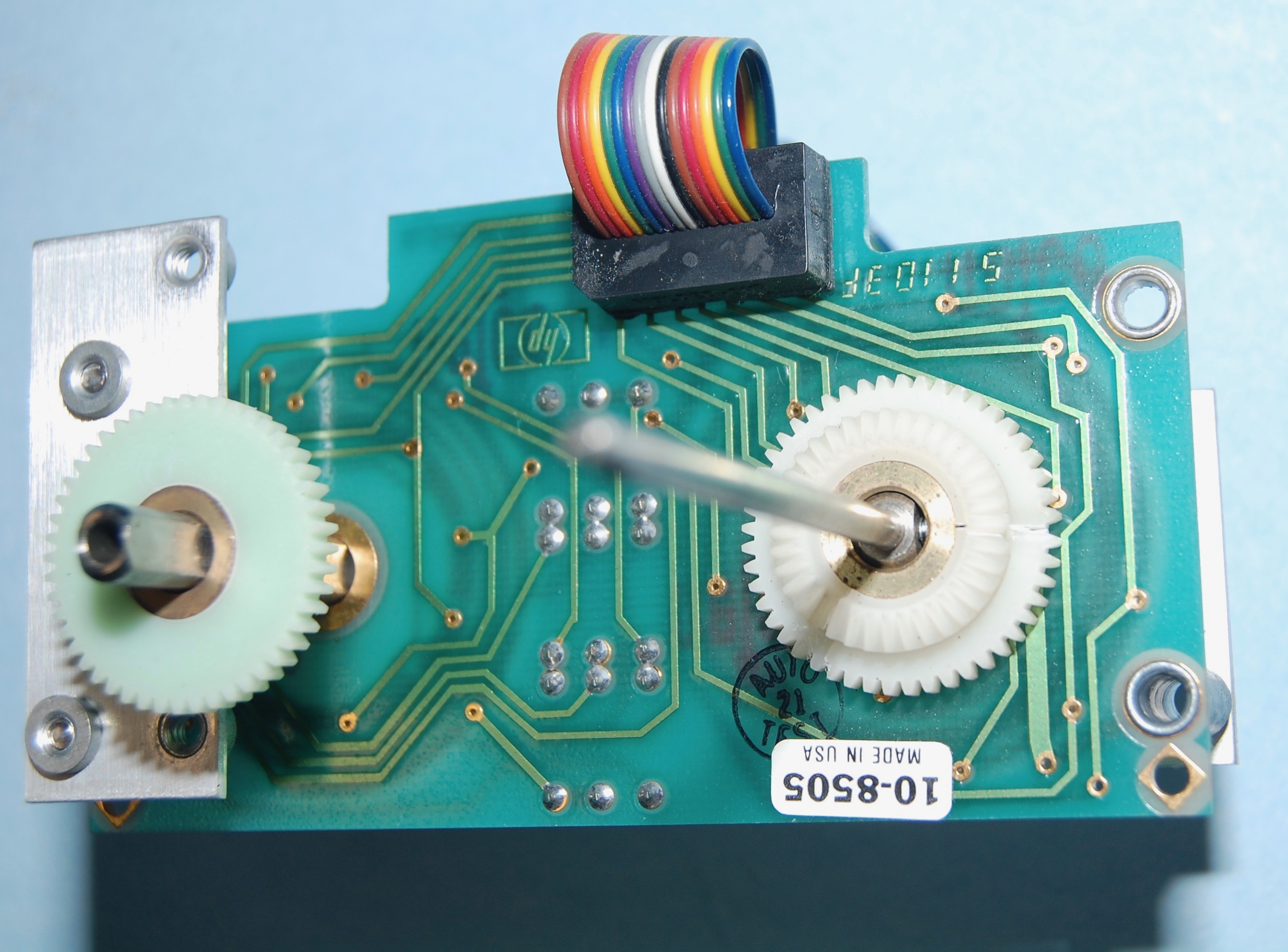
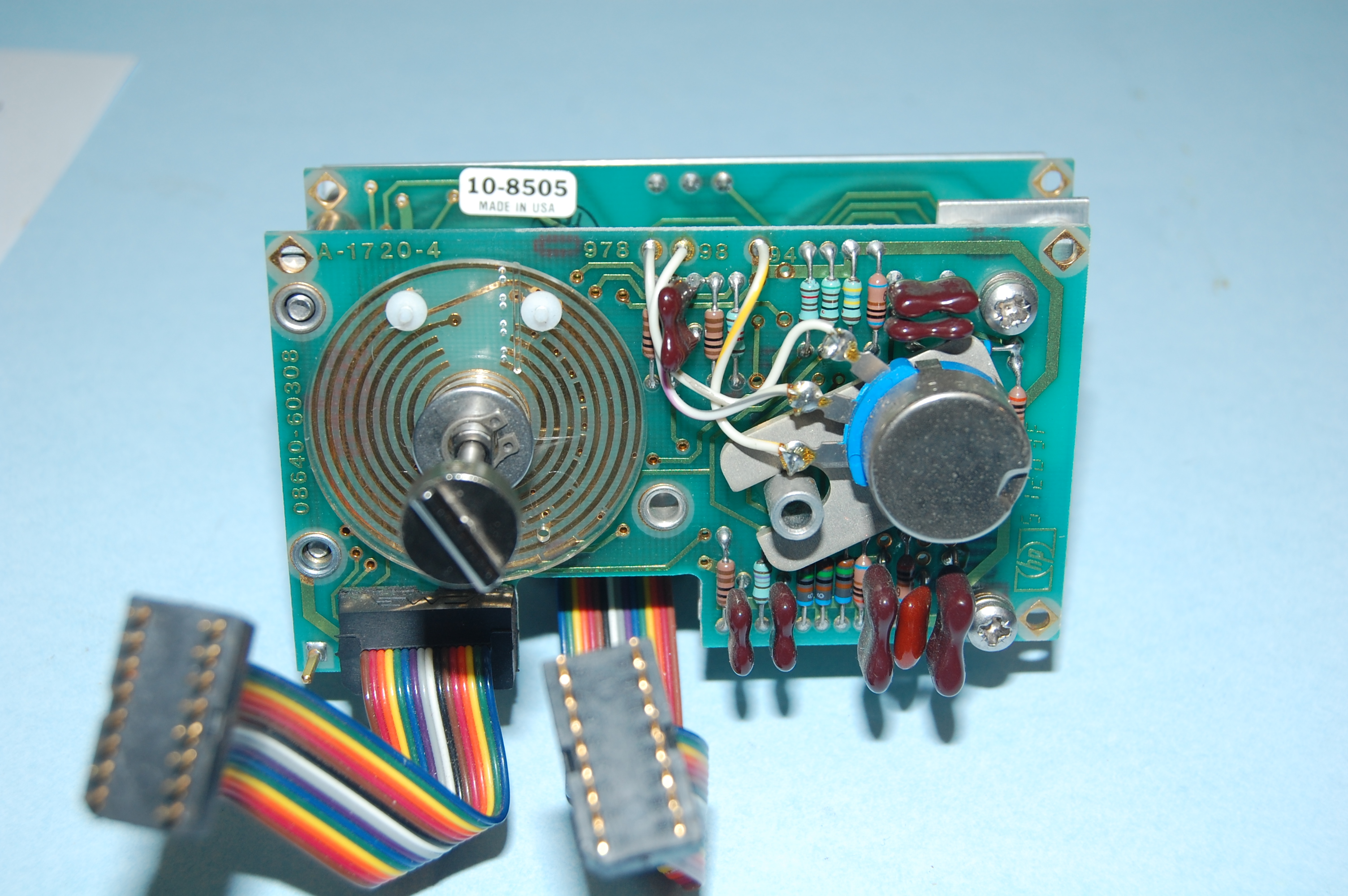
A9A1 and A9A2 Removal
NOTE
For the following steps, orient the switch asembly with A9A1W1 and A9A2W1 up.
Numbers in parentheses refer to items in the accompanying illustrated parts breakdown.
The scan page has been broken into two pages below to facilitate usage at full size on your monitor. And the parts page with part numbers for A9 is included.

Set both shafts fully ccs, and desolder the three wires attached to the potentiomter terminals.
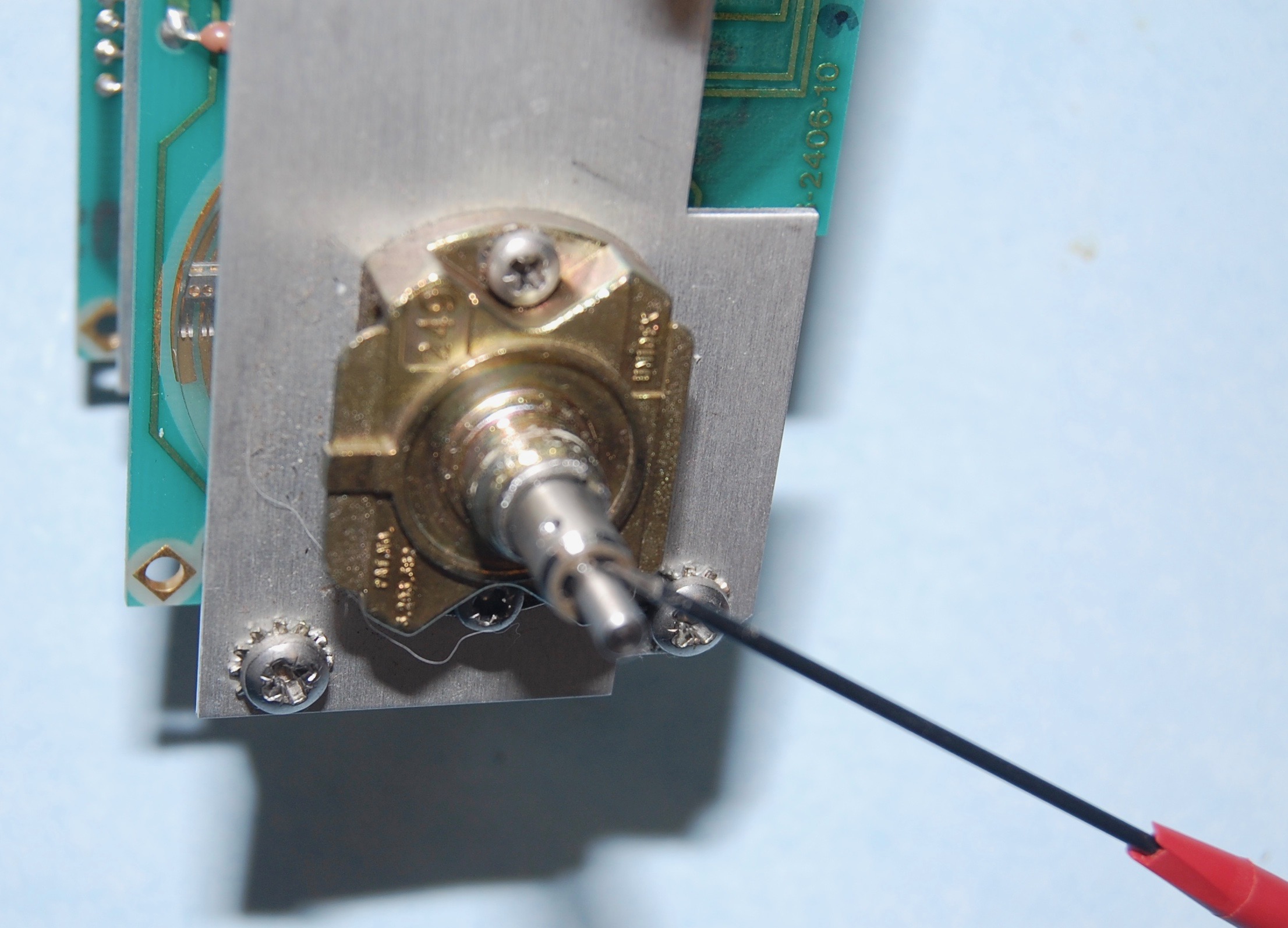
Remove retainer ring (49) at front of potentiometer shaft, and slide potentiometer and its mounting plate out to the rear of the switch.
This is a 'D' clip and easy to pry off.
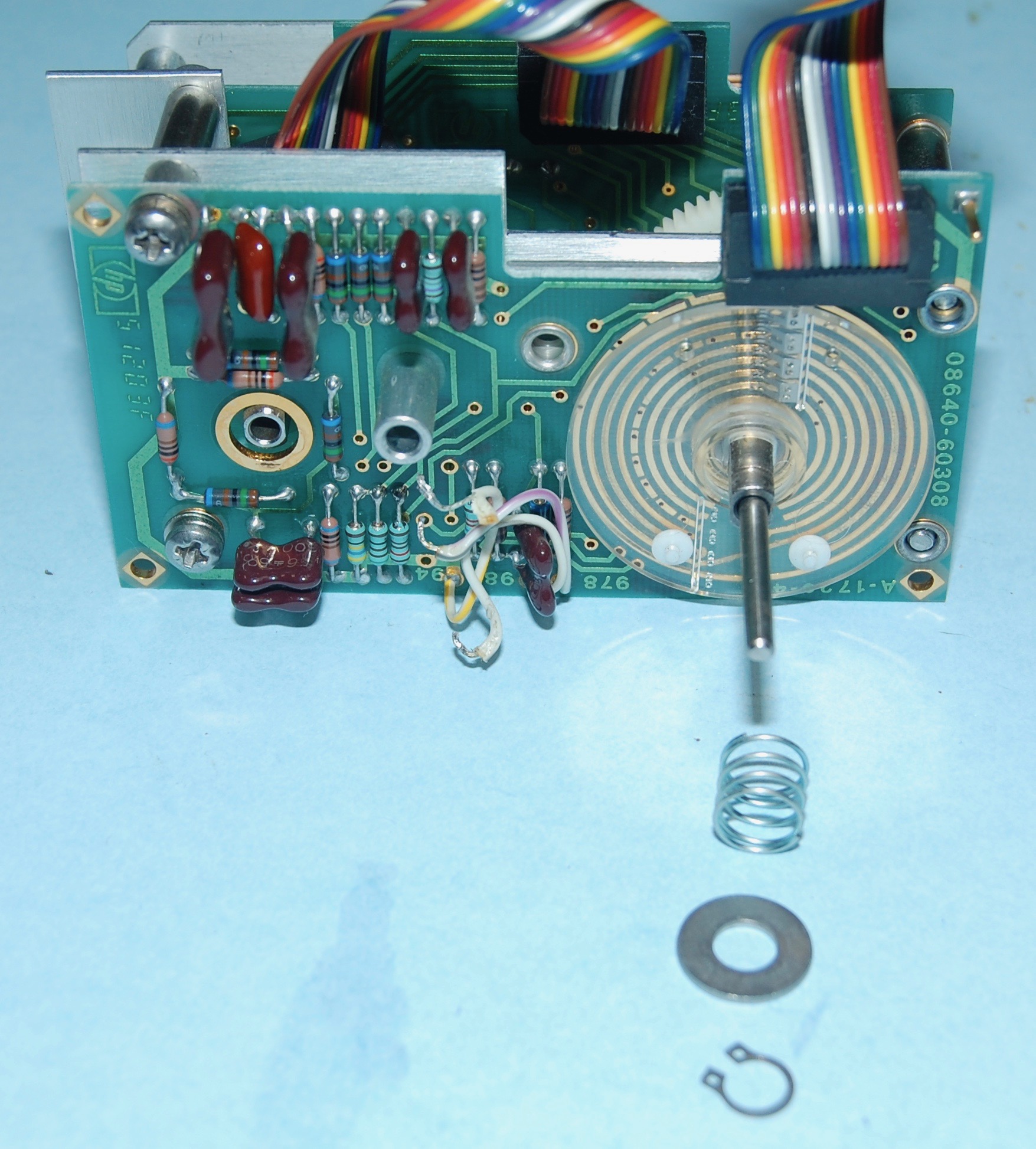
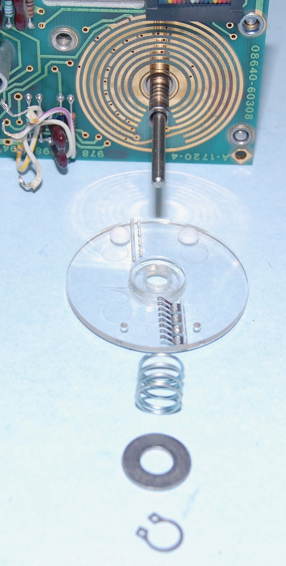
Remove retainer ring (1), washer (25), spring (24), and 4-contact rotor (23) at right rear of switch.
This, however, is a real external snapring. The trick is not messing anything up removing.
Remove two machine screws with lock and flat washers (31, 34, and 35) at right rear of switch. Remove two machine screws (2 and 8) and accompanying spacers (18) located at front left of switch.
Slide A9A2 Assembly (36) and gear mounting plate (37) off of detents shafts.
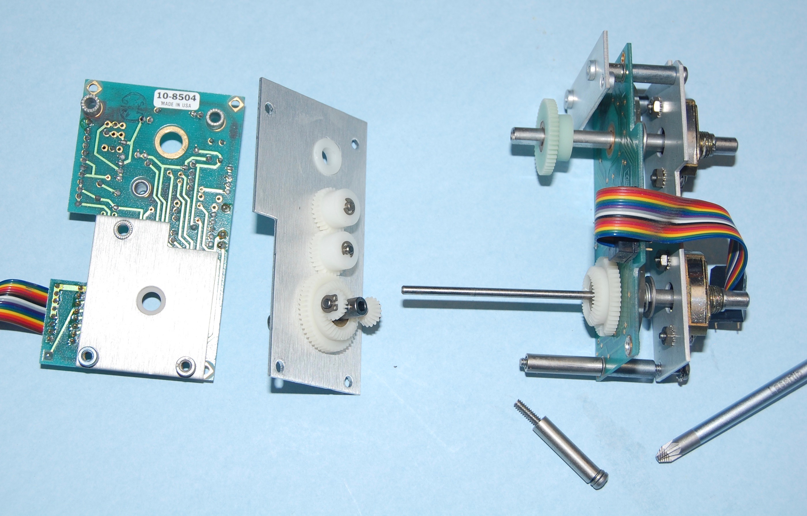
Slide T-shaft (17) with its accompanying combination gear (19) and planet gears (15 and 42) off of solid shaft (part of 50).

Loosen setscrews and remove combination gear (13) from solid shaft.
Loosen setscrews and remove spur gear (40) from hollow shaft (part of 47).
If you're just doing the gears stop here.
Remove two machine screws (46) at front right of detent monting plate (4), and remove P.C. board support (41).
Slide A9A1 Assembly (11) off of detent shafts.
- Reassemble A9 Assembly by reversing steps 6 through 15 above, while observing the followin points:
- If the shaft index assemblies (47 and 50) were removed, mount them with the index tab pointing to the top of the switch. Mount the hollow shaft on the right side. When assembly is complete, check to be sure the shafts do not bind against the P.C. boards. If the shafts ind, loosen mounting screws (48) to adjust.
- Set detent shafts fully ccw.
- Install both the 3-contact rotor (9) and the 2-contact rotor (43) with contacts aligned vertyically and toward the bottom of the switch.
- Set the rear, 4-contact rotor with contacts aligned vertically and pointing toward the top of the switch. This adjustment is made by loosening the set screws on the combination gear (13) to reset the rotor position.
- FM Deviation and Counter lights must be vertyical after A9 is reassembled.

Service Sheet D . 8D-9
A9 Reassembly
8D-10 . Service Sheet D