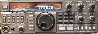
TS-430s IF filter mod


The Kenwood TS-430s allows for great flexibility in selecting different IF filters. It comes with a 2.4 kHz (6 dB) wide filter for SSB and CW and has a slot for both narrow SSB (1.8 kHz) and narrow CW (either 270 or 500 Hz) filters. In addition, a 6 kHz wide filter is available for AM.
The filters are automatically selected according to the mode selection (CW, USB, LSB, etc.) and according to the narrow/wide switch. One limitation of this is that the narrow CW filter cannot be used in the LSB mode. Most RTTY operation with this rig will be done in the LSB mode, and having a narrower filter would reduce the effects of QRN and QRM.
The original circuit (fig. 1A) uses a diode switching approach to select the appropriate filter. Connector No. 27 (may be labeled No. 29 in the instruction manual) comes from the narrow/wide switch on the front panel. Either of the control lines SSW or CWW go high in the wide position, depending on the mode (SSB or CW respectively). Similarly, SSN or CWN go high in the narrow position, according to the mode selected. These control lines connect through resistors (and sometimes diodes) to the appropriate IF filter. A modified circuit (fig. 1B) is shown which allows for the use of the narrow CW filter in the SSB mode. In the LSB mode, in particular, this filter ends up being centered around an audio frequency of about 2 kHz, which is ideal for RTTY interfaces using audio tones in that area. The IF shift control can be used to adjust this frequency, if necessary.
In normal transceiver operation, switching from CW or SSB often results in the narrow position selected in the SSB mode. If no narrow SSB filter is installed, the IF section is simply left open and no signals can be heard. The suggested but untested circuit shown in fig. 1C will enable the wide filter in SSB mode regardless of the narrow/wide switch position. To locate the appropriate area inside the transceiver, follow the instructions for installing the optional filters. R7 and R8 are located towards the rear of the IF filters. The ends of R7 and R8 nearest the rear of the transceiver go to connector No. 27. (Be careful in unsoldering the resistors because the printed circuit board traces are delicate.)
Robert A. Witte, KB0CY
from Ham Radio, May 1984, p. 125