The TS-120S may exhibit intermittent oscillation on the 15M,
10M, and/or 20M bands. Symptoms may be no control of Carrier
level, full current or ALC in either CW or SSB after initial
keying or modulation, or "full output both forward and reflected".
Physically disconnect power from the radio.
Make certain the Antenna fitting is tight to the rear panel.
Remove covers. Unplug speaker lead.
Check for loose screws securing the RF unit X44-1260-01
and the relay unit X41-1250-00 (located over the RF unit).
On the RF unit, check diodes D2, 3 and 8 for high reverse
leakage. If in doubt, replace.
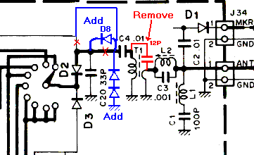
If not already present on the RF unit, make the following
chanqes:
R47 (33 OHMS change to 10 OHMS Radial (RD12CY2ElOOJ)
R50 (560 OHMS) change to 680 OHMS Radial (RD12CY2E681J)
C61 (220 PF) Remove
Add 2 1S1587 (V11-0370-05) diodes in series, anode to
ground from the junction of C4 and D8.
NOTE: Diode I.D. 1S1587 = 1S1585
Added diodes may induce RX IMD. If so delete.
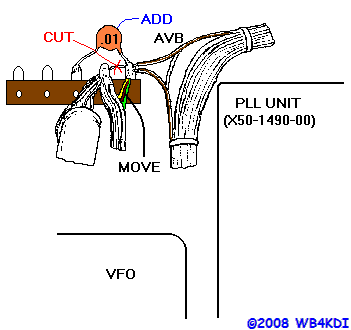
As illustrated, carefully cut the cable ties on the wire
harness (without cutting the wires) as it rounds the corner
behind the PLL unit X50-1490-00.
Seperate the AVB line, a white/brown line from the filter
unit X51-1200-00 to the RF unit X44-1260-01
Adjacent to the rear of the PLL and to the left you will
see a five pin terminal strip. The two right-hand most
terminals are bridged. WITHOUT BREAKING THE TERMINAL OR
STRIP, remove the heavy yellow, and light red and green
lines and transfer them to the adjacent terminal. There
will now be seven lines, plus the positive end of C1
on the second terminal. Be sure to cut the wire jumper
between these two terminals.
The free terminal will be a tie point for the AVB line
bypass capacitor. Solder a .01uF 50V disc ceramic
(C52-1710-36) between ground and the first free terminal.
Use spaghetti to insulate the leads. Then solder the
AVB line to the .01uF cap.
Retie the cable harness with nylon cable ties (J61-0401-05).
Replace the covers and speaker lead. Power-up and verify
correct operation.

 As illustrated, carefully cut the cable ties on the wire
harness (without cutting the wires) as it rounds the corner
behind the PLL unit X50-1490-00.
As illustrated, carefully cut the cable ties on the wire
harness (without cutting the wires) as it rounds the corner
behind the PLL unit X50-1490-00.