June 1948
Conversion of SCR-274N Receivers
Simple methods for converting receivers of the 274 series and extending their ranges
By C. W. ROESCHKE, W5MLX
The receivers of the SCR-274 series including the ARC-5 Navy version, offer the advantage of excellent construction combined with good performance. Little conversion is required to adapt these receivers to either a.c. or mobile operation, and inasmuch as the per unit cost is low, several may be purchased and used as auxiliary or standby units.
These receivers are supplied in four frequency ranges which may be readily identified by the model number. The BC-453 covers the range of 190 to 550 kc., the BC-946 covers 520 to 1500 kc., while the BC-454 covers from 3.0 to 6.0 mc. The range from 6.0 to 9.1 mc. is covered by the BC-455. These receivers all have the same general appearance and construction, and the only essential difference lies in the i.f. frequencies and frequency ranges. The circuit shown in Fig. 4 is typical of all the receivers in this series. Minor differences are in the tuning capacities and the values of a few parts.
There are several methods of conversion that may be used, depending on the results desired. As the receivers are supplied for 28 volt d.c. operation, if batteries or a power supply are available to furnish this voltage and the receiver is equipped with the original dynamotor, no changes at all are necessary. However, it is doubtful if many users will care to operate the receivers under this condition.
The tube lineup of the receivers consists of a 12SK7 r.f. stage, a 12K8 oscillator-mixer, two 12SK7's as i.f. amplifiers, a 12SR7 as a combined second detector and b.f.o., and a 12A6 output stage. The heaters of the tubes are wired in series in pairs, permitting use on a 24 to 28 volt heater supply.
If a 24 to 28 volt transformer, capable of furnishing one-half ampere is available, the filament circuit need not be rewired. Recently there have been several transformers of this type advertised. There are also combination transformers available which are capable of furnishing the necessary plate voltage.
In the event that it is desired to use a transformer of the standard type, it will be necessary to rewire the heaters so that the heaters are all in parallel.
The first step in this conversion is the removal of the bottom plate, easily accomplished by the removal of the screws holding it in place. The tubular condensers and other components mounted along the sides of the chassis should also be removed and allowed to hang over the sides of the chassis. The leads to these components should not be removed, as they will be replaced when the conversion is complete. The heater wiring may be easily traced by following the diagrams in Figs. 3 and 4. One terminal of each heater should be grounded, and a common lead run to the other heater terminals.

A 50,000 ohm wirewound control is the value found most satisfactory in this position. The control selected should have a taper designed for control of cathode bias. The b.f.o. on-off switch is connected between terminals 5 and 2 on the control plug. The standby switch is connected from terminal 7 and terminal 2, and serves to ground the center terminal of the power transformer secondary shown in Fig. 7.
The audio output of the receivers is rather low, but is sufficient to drive a small speaker or a pair of headphones. A phone jack may be mounted on the side of the chassis, and connected to terminal 4 of the control plug. The frame of the jack should be grounded to the chassis.
Normally the receivers are supplied with the output transformer connected for high impedance (8000 ohm) output. A tap on the output transformer permits the matching of 600 ohm loads. With the majority of headphones in use, the high impedance tap is the proper one, and the connections of the output transformer should be examined to see which connections are used.
With the alterations listed to this point, the receiver is ready for service, with the proper source of power. A satisfactory a.c. supply is shown in Fig. 7.
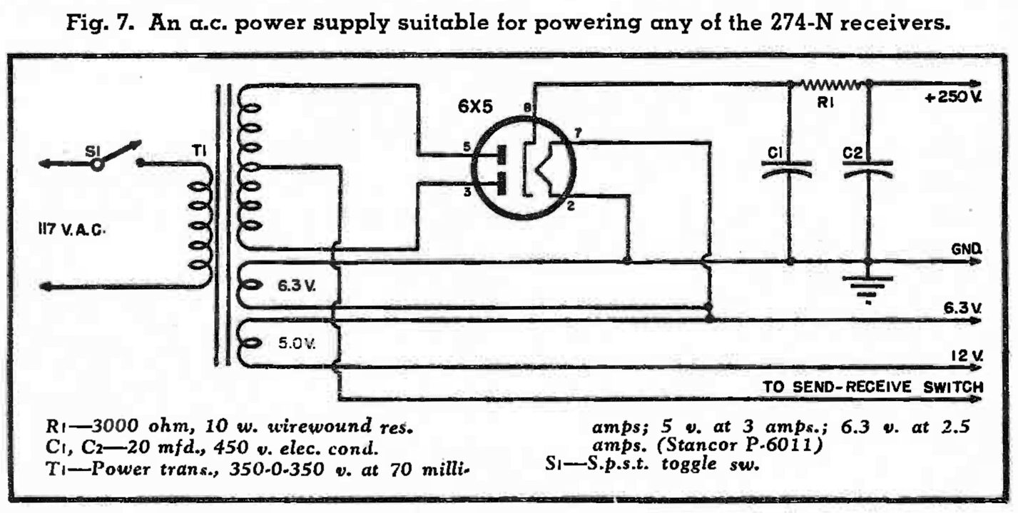
A 6X5 rectifier is used to eliminate the need for the normal rectifier winding. The use of a dual-section filter condenser provides adequate hum free d.c. from the power supply.
In the event it is desired to change over to six volt tubes, all the tubes used in these receivers have equivalents in the six volt series, with the exception of the 12A6. A 6V6 may be used in its stead with no circuit changes.
Photos of two different conversions are shown. The one in Fig. 5 includes an a.c. power supply and an "outboard" ten meter converter.


In this conversion, the left hand toggle switch controls the "B" supply of the auto radio, the knob in the center is the audio gain control, and the right hand toggle serves to place the noise limiter in or out of the circuit. The output transformer has been replaced by one of the midget universal types, to match the output tube to the two inch speaker mounted in the space formerly occupied by the dynamotor.
So far this article has dealt only with the conversion necessary to use these receivers on their original frequencies. The BC-453 and BC-946 do not have much appeal for high frequency work due to the low i.f. frequency, although they both have excellent selectivity.
The i.f. frequency of the BC-454 is 1415 kc. while the BC 455 uses an i.f. of 2830 kc. With i.f. frequencies of this order, excellent image rejection is achieved. This is especially important if the receivers are to be converted to the ten meter band. There are two possible methods of changing the receiver frequencies. The simplest method is the rewinding of the coils to cover the ten meter band. This method has the disadvantage of making the receiver useless on its original frequency as well as creating problems of cut and try to obtain the proper tracking over the band. While this is not too difficult if the proper equipment is on hand, few amateurs have the necessary instruments and experience to obtain optimum results.
A far more satisfactory method of using the receivers on ten meters is the use of a broad-band converter. By this means, the original calibration and tracking of the receiver is not disturbed, greater over-all stability is obtained, and considerable gain results. No added controls are necessary, and the converter may be constructed in a very limited space.
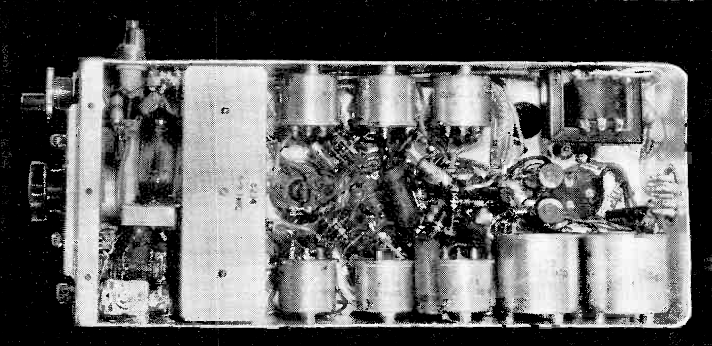
In this version, the entire converter is built into a cut down i.f. can and mounted at the side of the receiver. The socket for the 6J6 converter tube is mounted on the top of the can while the two screws on the side of the can are the slugs used to tune the coils in the input and oscillator circuit.
The entire converter is mounted on a bracket of aluminum which is fastened to the receiver chassis by means of short machine screws. The condenser used to tune the antenna circuit and permit matching is on the rear of the can and is not visible in the photos.
The diagram of the converter portion is shown in Fig. 6.
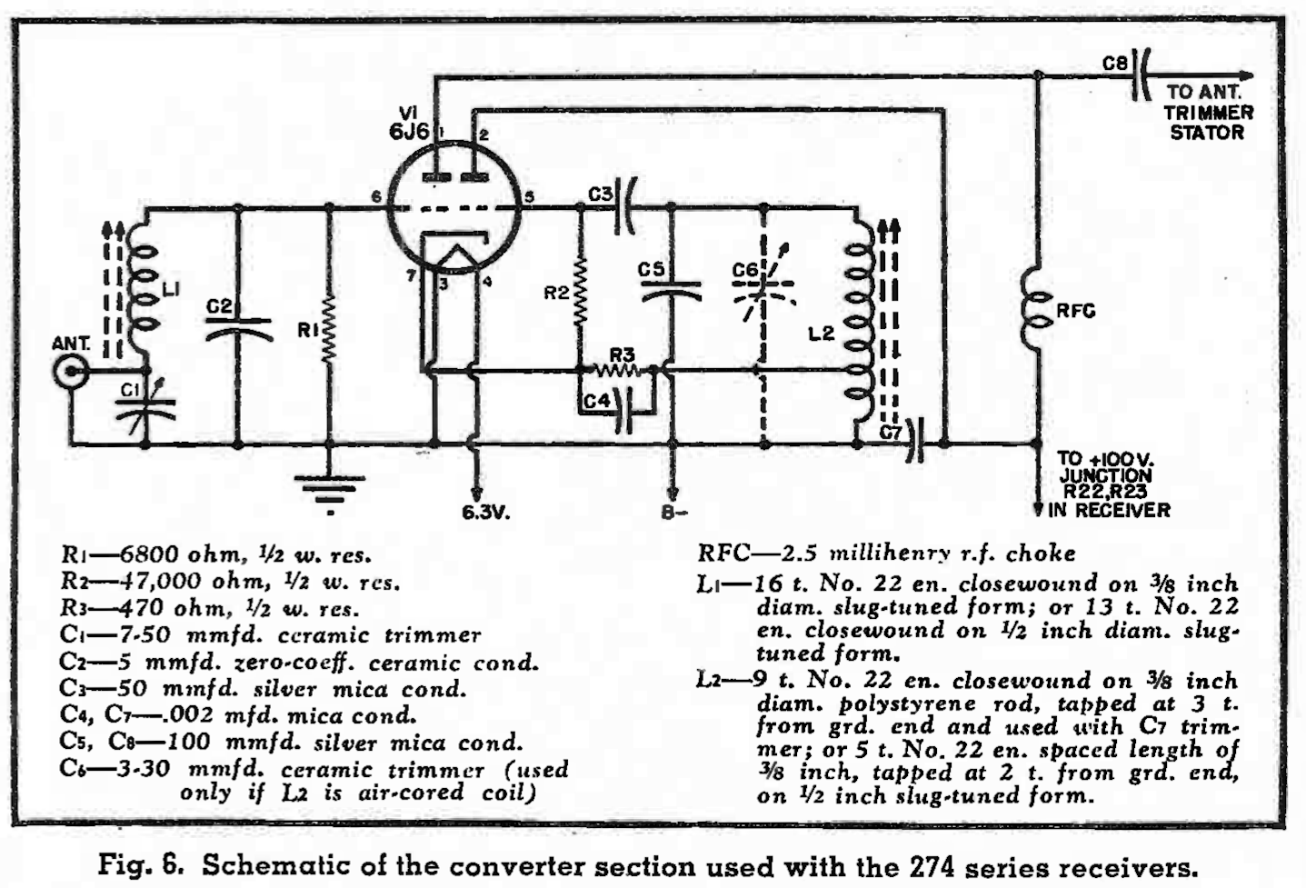
A 6J6 was selected as a combined mixer and oscillator. A triode mixer has a very favorable signal-to-noise ratio, and the stability of the 6J6 ap an oscillator is excellent. As the 6J6 has only one cathode, the oscillator grid leak R2 is returned directly to the cathode, while bias for the mixer portion is developed across the resistor R3 in series with the cathode tap on the oscillator coil.
The oscillator coil may be either of the slug-tuned type or wound on a piece of rod or tube. A slug-tuned coil is preferable as the bugaboo of adjusting to the proper value by spacing turns or squeezing, is eliminated. In the event an air core coil is used in this position, it will be necessary to use a variable trimmer condenser across the coil to permit setting the frequency.
The plate of the mixer portion of the 6J6 is connected directly to the stator of the trimmer condenser mounted at the left of the receiver. A 2.5 millihenry r.f., choke acts as a plate load for the mixer.
Input to the converter is through a connector of the type sold for auto radio use. This permits the use of a coaxial type feeder and allows rapid disconunection if the receiver is to be used on its original frequency.
The shielding of these receivers is excellent, and this is of the utmost importance if a converter is to be used. In one version, pickup of signals on the original range of the receiver was eliminated by removal of the antenna post. In the other version, the post was shielded by means of a small can made from a defunct electrolytic condenser. This can may be removed simply by removing one screw and the antenna connected to the post. The receiver may then be used on its original frequency.
An explanation of the operation of this type of converter is probably in order. The input circuit, consisting of the band of 27 to 30 mc. The oscillator circuit is tuned to a frequency depending on the original range of the receiver. In the case of the BC-454, the oscillator is tuned to a frequency of 24 mc., while for the BC-455, the oscillator operates on 21 mc. Incoming signals in the range of 27 to 30 mc. beat with the oscillator frequency, and the regular tuning dial of the receiver is used. As the receiver in itself is selective, only a narrow band of frequencies is passed by the receiver, in the same manner in which the receiver operates by itself. The selectivity of the entire unit is exactly the same as the receiver itself. In effect the receiver acts as a tunable i.f. chanel. This is essentially the same method used in the new Collins receiver. As the effective i.f. frequency is high, there is no difficulty with image response.
Determination of the received frequency is simple if it is remembered that the receiver dial will indicate this value simply by adding the frequency of the oscillator to that appearing on the dial. For example if a BC-454 is used, and the receiver dial indicates 5 mc. on a received signal, the frequency of that signal is 5 plus the converter oscillator frequency of 24 mc. or 29 mc. As the converter oscillator is fixed-tuned, it is possible to make it very stable with the result that there is no drift and the calibration does not change.
The two receivers converted were both purchased equipped with tuning cranks. Most receivers however, are sold minus these cranks, and in this event it will either be necessary to purchase these cranks in surplus, or use some other method of tuning. There are several possibilities. One is the removal of the threaded sleeve, and the use of a standard 1/4 inch shaft coupling. A piece of 1/4 inch i.d. brass or copper tubing, if squeezed slightly, will be a snug fit on the dial shaft. A piece of 1/4 inch shaft may then be placed in the free end of the tubing and soldered in place. Any type of knob may then be used.
If a.v.c. is added to the receiver, it will be necessary to provide an audio gain control, in place of the r.f. gain normally used. The wiring leading to this control should be shielded, as well as the wiring to the noise limiter switch if a noise limiter is used, The noise limiter does not introduce noticeable distortion, and the inclusion of such a switch is not absolutely necessary.
A 1N34 crystal was used as the noise limiter, but it would be preferable to use a diode such as a 6AL5 or 6H6. The disadvantage of the crystals lies in their relatively low reverse resistance, which acts as a load on the detector circuit, reducing the effectiveness of the limiter. Some crystals will be found to give con- siderably better performance in this circuit than others, and if several are available, the best one should be selected. If a tube is used, the cathode of the tube goes to the audio coupling condenser, C10. The point at which the limiter operates may be changed by changing the value of R14. Increasing the value of this resistor will result in greater limiting action, but the distortion will also increase.
If it is desired to use one of the fixed-tuned converters to extend the range of the receiver to the ten meter band, the input and oscillator coils should be mounted at right angles, or shielded from each other. There is sufficient coupling between the two sections of the tube to give satisfactory injection, and no provision need be made for any adjustment of injection. Triode converters are noticeably free from a critical value of injection voltage.
If a converter is used, the adjustment is simplicity itself. When construction has been completed, the frequency of the converter oscillator should be set, by adjustment of the tuning slug if a slug-tuned coil is used, or adjustment of the padding condenser if an air core coil is used. If the receiver used is a BC-454, the oscillator should be set to 24 mc. If a BC-455, the oscillator should be placed on 21 mc. A calibrated receiver or frequency meter will considerable assistance in this operation.
An antenna should then be connected to the converter and the receiver tuned until a signal is heard. The station transmitter used with a dummy load, or a modulated signal generator may be used to furnish the signal in the event no stations can be heard. When the signal has been tuned in, the coil slug and antenna condenser C1 should be adjusted simultaneously for maximum signal strength.
When the adjustment has been completed, the signal may be peaked by means of the antenna trimmer on the receiver. This trimmer will require little or no adjustment in tuning over the band.
All tuning is done with the regular dial, and the converter will require no further attention or tuning unless an antenna system with a different feeder impedance is used.
Of the two receivers converted, the BC-454 gave somewhat better performance. Selectivity of this receiver is also somewhat better, being in the vicinity of 7.5 kc. at two times down.
C. W. ROESCHKE, W5MLX
from Radio News, June 1948, pages 49-51 and 162-165