
January 1956
The Novice Q5'er

Want $500 rcvr performance at 1/20 the price?
Donald L. Stoner, W6TNS
Assistant Professor of Electronics, Chaffey College, Ontario, Callifornia
How would you like a receiver that doesn't drift? A receiver that is sharper than a double edged razor blade? Not only that, but a receiver that will give your arm a charley-horse before you can tune the 40 meter band? If your purse can stand $20.00, it can be yours. Before you mumble something about a babbling idiot and flip the page, read on MacDuff.
About two months ago, I was batting the breeze with KN6HGY. Art has had his ticket 8 months now and hasn't had a solid contact yet. It seems he was getting out fine, but after standing by for a station his receiver had drifted off the station completely. I invited myself over to his shack to see what the trouble was. Sure enough, all I had to do was set the receiver on 7185 and I could hear every station in the novice band. It sounded like the parakeet corner at the local pet shop. As I reached for the dials, the squawks changed and in came W6ZZY calling CQ 40 on 7210. "Boy, this inhaler has flipped its lid, Art," I said. "Looks like you're ready for a new "Blooper 8". "Ha! The treasury is flatter than a cherry red 6L6," said Art. "Looks like I'm off the air until I can afford one".
That night I started thinking. How many Novices and even general class hams were in this boat?
Well after copious pots of coffee, 13 ball-point refills, a dozen Weller tips and a near divorce, here is what I came up with: The Novice Q5'er. This receiver was stacked up with several commercial receivers and proved to be as good as any and superior to several. The heart of the receiver is the BC-453 Command receiver. This receiver has 6 tubes and tunes a frequency range of 190 to 550 kilocycles. "This is good?", you say. You bet it is, and here's why.
If we amplify the radio signals that the antenna picks up, at a low frequency, we can increase the selectivity. Increased selectivity means that signals off the side of the station we are trying to copy will not be amplified. Suppose the radio amplifiers were 3 percent of their dial frequency wide. If our receiver had 455 kc amplifiers, they would be 13.6 kc wide. This means that we could hear stations that were 6.8 kilocycles either side of the station we are trying to copy. If we lowered the frequency of the amplifiers to 85 kc, what is the bandwidth now? Three percent of 85 kilocycles figures out to be 2.5 kc. Now Joe Novice has to be within 1.3 kilocycles of the station we are receiving to cause any interference.

What about stability? Well the Novice Q5'er is rock solid. It just doesn't drift. If the receiver is working correctly, and has had a ten minute warm-up, it won't drift over 200 cycles. You can beat on it with an old 304TL and it will never change pitch on CW. The reason for the stability is the low frequency amplifiers again. If the percentage of drift in a receiver stays the same, then as we go lower in frequency with the amplifiers, the number of cycles of drift will be lower. Of course, Uncle Sam did a doggone good job when he designed the command set series.
About this time you are probably wondering if the FCC opened a new ham band somewhere between 190 and 550 kc. Not yet, we are interested in 40 and 80 meters. Therefore, we must convert the signals to a frequency that the BC-453 can receive. This is accomplished by a method called heterodyning. Briefly, heterodyning is the mixing of two frequencies to produce a new frequency.
After the signal has been amplified to a sufficient level, it is detected. This means we remove the intelligence from the carrier. (That's what carried it to our antenna from Joe Novice.) In the case of phone reception it involves removing changes in carrier strength that constitutes the other person's voice. These changes in carrier strength are further amplified in an audio amplifier until they are strong enough to vibrate your speaker or head phones.
For code reception, something different happens. There are no changes in amplitude, only intermittent dots and dashes. We are unable to hear the dots and dashes, so we call on Mr. Heterodyne again. By generating another signal at 86 kilocycles, we produce a new signal at 1 kc or 1000 cycles. We are able to hear the 1 kc signal and it appears in our phones each time Joe Novice presses his key. That's all there is to it, this heterodyning deal holds true for any superheterodyne receiver.
Let's still generate that 6800 kc signal but this time listen for a signal at 7300 kc (the high end of the 40 meter band). Now what happens? 7300 minus 6800 equals 500 kc. Crank the BC-453 dial up to 500 kilocycles and we are hearing 7300 kc. I might mention that it takes 24 turns of the dial and 4 seconds is the record. If the 6800 kilocycle signal we generate is crystal controlled, there will be no noticeable drift in this part of the circuit.
Sounds pretty good doesn't it? How can you build this double conversion inhaler for 25 bux ? Easy, most of the work has been done already when you buy the BC-453. The Navy version the R23/ARC 5 will work as well by the way. Either receiver will sell for about $10, leaving $15 for the converter and BC-453 conversioin parts.
The components necessary to convert the BC-453 to a-c operation will amount to about $6.00. The necessary conversion information has been covered very well in earlier issues of CQ.1 Therefore, I will only detail some of the refinements that make a professional looking job. About the best conversion uses a small 6 tube radio transformer connected to provide 11.3 volts a.c. This allows the constructor to use the original 12 volt tubes. The schematic of the Q5'er power supply is shown in Figure 1. (Updated 8/2021. Be sure to jumper 6 and 7 of J1 in the front of the BC-453 to enable the filaments supply.)
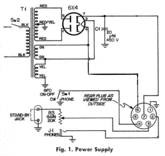
| Power Supply Parts List | |
|---|---|
| C1 | 20 μfd. 450 WVDC |
| R3 | 20,000 ohm pot. with SPST switch |
| S1 | SPST Toggle switch |
| S2 | SPST switch, part of R3 |
| J1 | Open circuit phone jack |
| J2 | 2 Screw terminal strip |
| T1 | Small receiver power transformer. 250-0-250 volts @ 50 ma. 6.3 volts @ 3 amps. 5.0 volts @ 2 amps. |
To do a professional job, don't use a separate power supply. All the components can be
mounted on the rear apron of the BC-453, after it has been cleared of obstructions such as the
dynamotor plug and shock mounts. (Times change. Use an external power supply and don't modify the rear apron of the BC-453.)

A phone jack, gain control, and toggle switch can be mounted on the front panel if a small plate of aluminum is drilled as shown in Figure 3. It is a tight squeeze, but they will all fit. Actually, if the two pillars and knob are drilled off the original front plate, the parts can be mounted in these holes after they have been enlarged.
A two screw terminal strip is mounted on the rear apron of the Q5'er. One lug is connected to the ground end of the gain control and the other lug is grounded. During normal operation these lugs are connected together. If a signal pole, single throw switch is connected across the terminals it can be used as a standby switch or it could be connected to an extra set of contacts on the transmitter keying relay to mute the receiver whenever the key is pressed. If a 100 K ohm resistor is connected across those keying relay contacts the receiver will function while transmitting, but at a very low volume level. Therefore, the receiver will act as a monitor making it much easier to send good CW. Also, a 4-wire cable is brought out thru the side or rear of the receiver. This supplies 12 volts a.c. to the converter along with 250 volts d.c.
The Q5'er converter is very simple to build. It is diagramed in Figure 4. (Corrected 8/2021)
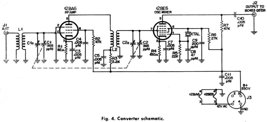
| PARTS LIST | |
|---|---|
| C1, C2 | Dual section 365 μμfd variable condenser |
| C3, C4, C5, C7, C10 | .005 μfd disc ceramic |
| C8 | 47 μμfd mica or disk ceramic |
| C9 | 200 μμfd disc ceramic |
| R1 | 82 ohms |
| R2 | 7 K ohms 1 watt |
| R3 | 2.2 K ohms 1 watt |
| R4 | 150 ohms |
| R5 | 22 K ohms |
| R6 | 27 K ohms |
| R7 | 47 K ohms |
| L1 | Antenna coil Miller #B 320 A |
| L2 | Mixer coil Miller #B 320 RF |
| J1 | Amphenol coaxial connector |
| J2 | RCA phono jack |
| J3 | Amphenol 4 pin female plug |
| XTAL | 3400 kc or 4200 kc for the 80 meter band |
| XTAL | 3300 kc or 4000 kc for the 80 meter band (3500 - 3800) |
| XTAL | 6800 kc or 7500 kc for the 40 meter band |
The signal emerges in the plate circuit of the 12BA6 greatly amplified and is coupled to the 12BE6 through a 50 μμfd capacitor. The crystal is connected to the oscillator section of the 12BE6 in such a manner that it supplies a steady oscillation for heterodyning. Capacitor C9 controls the feedback with 200 μμfd, an average value for crystals with average activity. All the crystals on hand oscillated readily in this circuit.
The converter layout is shown in Figure 5.
This size chassis will accommodate all the parts easily with no crowding. Although an L.M. Bender chassis is specified, any chassis with a surface area of 3 x 5 inches will do. This particular chassis is an L.M.B. #136. If a larger or a smaller chassis is used, no trouble will be encountered with placement of parts, the circuit is in no way critical.

To align the r-f section, the case must be removed. Under this is the tuning condenser cover with 3 holes in the top. The slot in the center adjusts the mixer section, the two at the side are oscillator adjustments. To adjust the r-f section, tune in a broadcast station at the high end of the band and peak up the "Align Input" knob and the mixer adjustment. Maximum signal on the broadcast station should fall exactly on the dial mark. If it does not, the oscillator is probably out of alignment. The Q5'er seems to hold its calibration nicely but if an LM or BC-221 signal generator is available it might be a good idea to check it. The adjustment nearest the front sets the low end of the band (190 kc) and the one toward the rear sets the high end of the band (550 kc). The next step is to connect the output of the converter to the input of the BC-453 and connect the power plug to the converter. The r-f section of the converter should be aligned at the 40 meter band. Don't forget to insert a crystal for 6800 or 7500 kc in the converter.
Turn off the b.f.o. and tune in a weak 40 meter phone station. Adjust the setting of variable capacitor Cl-C2 for maximum volume. After Cl-C2 is set, adjust the trimmer C1a and C2a for maximum signal. A final point should be reached where Cla and C2a peak up at one particular setting of Cl-C2. To check 80 meters, insert a crystal for 3400 or 4200 kc and retune C1-C2 for maximum signal. After the alignment is finished, all that need be done to change bands is insert the proper crystal and peak up C1-C2.
Some constructors might want to use a single pole single throw switch to change crystals, and this will work fine. I would prefer to insert crystals rather than be restricted to two bands. The converter will receive any frequency between 3 and 9 megacycles merely by inserting the appropriate crystal.
Well, now you're in business with a real receiver. Let's see if you can use it to obtain your general class license and work some DX too. The first station to come back to my CQ on this receiver was a VK2 in Australia. Maybe you'll have better luck.
Donald L. Stoner, W6TNS
from CQ Magazine, January 1956, pages 14 - 18