
December 1960
Here is a different approach to double sideband conversion of Command Transmitters from those previously proposed. This method was used with good success on both the ARC-5 and BC series of transmitters after difficulty was encountered in trying to convert them to operate as high-level balanced modulators.
Instead of connecting the 1625's as a balanced modulator, they were left connected in a normal fashion and operated as a linear amplifier. A low level balanced modulator using two 6V6 tubes was added on the back of the chassis in the sockets formally occupied by the tuning eye tube and crystal. The added modulator was then used to drive the linear amplifier. This method resulted in much improved operation since the low-level stage tended to act as a buffer stage between the oscillator and high-level stage. Previous attempts at trying to drive a high-level modulator with the existing oscillator in the transmitter had resulted in frequency modulation. Also the added tuned circuits of the linear amplifier gave increase harmonic reduction over the high-level modulator.
The conversion is not too difficult and may be completed in a couple of evenings by the use of the before and after schematic diagrams.


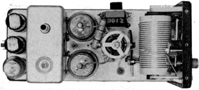
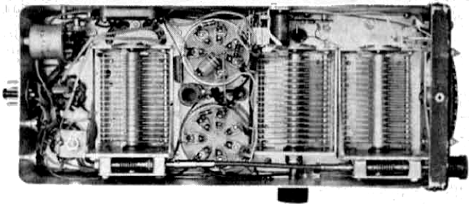
The two leads that formally ran to the grids of the 1625's and the neutralizing condenser should be re-routed to run to the sockets on the back. Pins 5 and 6 on each socket may he utilized to hold the 470 mmf blocking capacitors. The 10 K balancing pot may be mounted on the side or back of the chassis and the grid resistors run from pin 5 of the sockets to each side of the control. On the accompanying photographs, this pot is shown pointing out the bottom (since the author's arrangement utilized the standard rack for the transmitter).
Push-pull audio may be brought in the back plug and connected to the screens of the 6V6's. Each screen should be by-passed for rf with a 470 mmf condenser.
The plates of the 6V6's may be hooked in parallel and connected to the added tuned circuit. This coil may be added in the space between the 1625's and the oscillator tuning capacitor. The photos show the mounting detail of these components. On BC models of the Command Transmitters, it will be necessary to remount the final by-pass condenser on top of the chassis to make room for this coil. This coil should resonate in the center of the amateur band.
The grid circuit is changed slightly from the old Command Transmitter circuit to improve parasitic suppression. The old grid lead should be moved from pin 4 to pin 5 of each of the 1625's. The 47 ohm resistors may then be added between pins 4 and 5. The coupling capacitor may be hooked from the top of the tuned circuit to the bus wire. A small rf choke may be added from pin 2 of one of the 1625's to the bus wire to bring in grid bias. This completes the DSB conversion part of the transmitter. Relay and control circuits may be modified or added as needed.
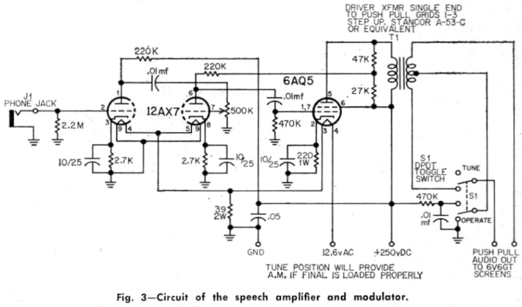
A schematic diagram of the speech amplifier used is shown but no constructional details are given. If good construction practice is followed in building it, no difficulty should be encountered. A tune-operate switch is provided so that carrier might be inserted to tunc the transmitter up. The "Tune" position of the tune-operate switch will also provide amplitude modulation.
A word should be said here about power supplies. K9DBO's axiom in March 1959 CQ applies here also (quole) "Good signals require good power supplies." The voltage applied to the oscillator should be well regulated by the use of series VR tubes. For best results. separate regulator tubes should be used for the 1625 screens and the oscillator; although a common regulated source did provide a satisfactory operation. The plate voltage may be anything from 300 to 750 volts. The ARRL Handbook may be consulted for the correct bias voltage for linear operation of the 1625's.
Initial tune-up procedure is not too difficult but does require the use of a scope and preferably an audio oscillator. The scope should be connected to provide a two-tone test pattern. The transmitter should be loaded into a dummy load in the tune position and the added slugtuned coil adjusted for maximum power output or cathode current. The tune-operate switch should be thrown to the operate position and a 400-1000 cycle audio note applied to the speech amplifier. The balance potentiometer should be adjusted until alternate lobes on the two-tone test pattern have equal amplitude. If an audio oscillator is not available, an alternate tune-up procedure is to couple the scope pickup loop tightly to the final tank. Turn the audio control to minimum and apply voltage to the transmitter. If the scope has good sensitivity, a small amount of carrier will appear as the balance control is rotated to either extreme. The balance control should be set for minimum carrier amplitude on the scope.
This completes the initial tune up. The transmitter should now be loaded into an antenna and the scope pattern watched as you speak into the microphone. Only the higher voice peaks should tend to be clipped or limited in the final. If heavy clipping is present. the drive to the final should be reduced by detuning the slug-tuned coil between the modulator and final (this might bother some of the purists. but it works). Heavy loading should be used on the final. If low-plate voltages (300-500 volts) are used, you might have to add another link to the final coil. This can consist of two or three turns of wire wrapped tightly around the bottom of the plate tank coil. If oscillations are present in the final, it might be necessary to add another .02 mmf by-pass condenser on the bottom of the plate tank. This condenser may be soldered in parallel with the remounted condenser that was originally in the transmitter. Additional screen by-passing may also be necessary. The parasitic and oscillation problem seems to vary from transmitter to transmitter.
You are now ready to get on the air and enjoy the advantages of sideband. True, most stations will receive you as a single sideband station and this gives you a 3 db disadvantage compared to a single sideband station of equal power. But, at least, you have gotten rid of the chief heterodyne cause, the carrier. Most of the sideband boys will not know you are transmitting both sidebands unless you tell them. Stations as far as 1200 miles away were worked with the converted transmitters running a peak power of only 35 walls. So if you have been looking for a cheap way to investigate this sideband business, here it is.
Richard G. Fenner, W5AVI
from CQ Magazine, February 1960, pages 50-52