
With the advent of SSB and the almost total disappearance of AM from the HF amateur bands, good SSB reception is mandatory. To date, a combination of hang-AGC and a product detector seems to be the best solution. The product detector is the most important element of this pair and numerous articles have appeared discussing vacuum tube versions of this worthy circuit. There has been very little information dealing with the design of a solid-state version, however.
This article will describe a design which is a transistor equivalent of the popular dual-triode product detector. It will discuss the causes of distortion to SSB signals which include BFO instability as a result of pulling, AGC non-linearity and inter-modulation distortion. As an example of these problems and their cure, it will refer to a product detector built for the Heathkit "Mohican".
In the GC-1A, the primary cause of distortion to SSB signals is BFO pulling. This phenomenon is the direct result of the presence of strong signals in the BFO circuit. In this receiver, the BFO output is injected at the input of the third if amplifier. This is done by connecting a 4.7-pf capacitor from the collector of the second if to a tap on the BFO inductor. Thus, any signal in the if strip is also in the tuned circuit of the BFO to some degree.
To understand why this will pull an osclllator, consider The tuned-grid, tuned-plate oscillator. It may be shown that in this oscillator, the tuned circuit with the higher "Q" will control the frequency. This is so because, a low "Q" tuned circuit having a broader frequency response, more feedback will be provided to the high "Q" circuit. Since feedback is the essence of oscillation, the tuned circuit getting the most feedback will control the frequency of oscillation.
By applying this logic to the BFO, it is easy to see how pulling occurs. If the BFO is treated as if it were a TGTP oscillator, then the incoming signal can be thought of as a tuned circuit with infinite "Q". With this situation the closer BFO gets to the signal frequency, or vice-versa, than, of the two feedbacks present, that from the signal and that from the BFO itself, the more predominate the signal becomes. At some point in tuning, it becomes the controlling feedback and the BFO shifts abruptly to the signal frequency.
When this occurs, the frequency difference between the signal and BFO is necessarilv zero. Since the desired audio output is that frequency difference, there can be no audio output. With an SSB signal, the peaks will be strong enough to pull the BFO leaving only the lower amplitude portions of the signal as output. The result is a highly punctuated garble.
With a diode detector, an output of a different but still useless nature is possible. A diode is a non-linear impedance, that is, the impedance varies as a function of the applied voltage or current. A fundamental principle of electronics states that an AC signal applied to a non-linear impedance will generate harmonics of itself. If two frequencies are applied simultaneously, they will also generate their sum and difference frequencies. When a signal as complex as an SSB signal meets a diode, the result is only slightly less calamitous than the famous meeting of the irresistabIe force-and the immovable object. In this situation, every audio component present may mix with every other audio component to form still more audio components. The result is the muffled, quacking, semi-speech with which we have become familiar with the rising popularity of SSB.
These components are also the output when the BFO locks onto one of the frequencies of an SSB signal. But even if the BFO stays where it should, these components are still present in the output of the diode mixer, because the diode must mix all frequency components present. This is where the product detector has a distinct advantage. It can mix only BFO and signal, rather than BFO and signal, signal and signal, etc. This type of distortion will be recognizable to hi-fi fans as inter-modulation distortion.
The AGC in a receiver can be another source of distortion. In receivers such as the GC-1A, AGC response is fairly fast, capable of following the syllabic rate of an SSB signal or the keying of fast CW. With a perfectly linear AGC, the only effect on an SSB signal will be uniform compression, or overall reduction of the dynamic range. If, however, the AGC response is not linear (which is likely since no tube or transistor has an infinite dynamic range) then the result will be envelope distrotion. This is a rearrangement of the relative amplitudes of the signal components. Normally, this distortion is not too severe as most signals will stay mainly within the most linear portion of the AGC response.
The more important problem with AGC is that, even without modification, it cannot be used effectively. If pulling occurs even with AGC, the AGC is not limiting the signal sufficiently and the only recourse is to reduce the RF gain. When this is done, the AGC begins to lose control and its advantages are gone. It is worth noting that for the GC-1A, Heath recommends that it be turned off for SSB reception.
The product detector is more properly known as a multiplicative mixer, the same circuit as is used for a converter in the front end of most modern receivers. This fact will explain the product detector circuits frequently seen which employ a pentagrid converter tube. Another apt name is "audio converter."
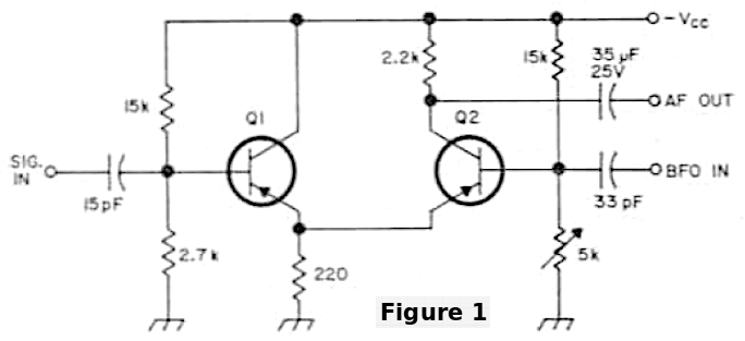
To see why and how a product detector works, refer to the circuit of Fig. 1. First, note that the coupling capacitors used have a very high reactance for transistor work, even at 455 kHz. The reactance of the 15-pF capacitor is about 20 kohm and that of the 33 pF is about half that. These high impedances are in series with the low input impedances of the transistors, providing a large voltage division. This insures small signal operation of the transistors guaranteeing their linearity.
This also provides a high degree of isolation for the BFO, which combined with the isolation inherent in the transistor, makes the BFO far more immune to pulling. This immunity is such that in the GC-1A, a local broadcast station about a mile distant, will not pull the oscillator more than about 50 Hz.
In operation, Q1 is an emitter follower, whose vacuum tube corollary is the cathode follower. The same conditions hold true for both. They are capable of power gain, but not voltage gain. Since the emitter resistor is common to the emitter of both transistors, the signal is directly coupled to what is to it, a common-base amplifier. In this amplifier, voltage gain is dependent to a certain extent on the quiescent or operating point of the transistor. This operating point is a function of biasing and the bias may be controlled at the base.
Since the BFO is connected to the base of Q2, it is constantly changing the bias and, therefore, the quiescent point at a rate near the frequency of the signal on the emitter. This means that the signal sees a linear input impedance and a rapidly changing voltage gain. This is the reason for the term, 'multiplicative'. Since the output voltage is the input voltage multiplied by the voltage gain, if we must inlcude the BFO frequency to express the voltage gain in the equation, then the effect is literally multiplicative mixing.
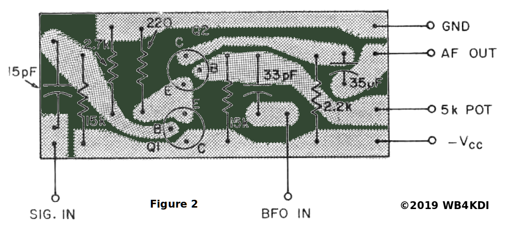
Having constructed the circuit, it should be mounted in the receiver and connections made to it. The supply voltage may range from six to twelve volts but be sure that you do not exceed the collector breakdown ratings of the transistor you use. The BFO should be able to supply about .2 volts RMS to the base of Q2 and the signal should not exceed this value at the base of Q1. These values are valid for the circuit when it is correctly adjusted.
To adjust the product detector, first set the linearity pot to zero resistance (so that the base of Q2 is shorted to ground ). With the BFO off, (making sure that the product detector is on adjust the linearity pot from zero until the signal to which your are tuned becomes slightly audible with the volume control on full. A local broadcast station makes an excellent test signal. When the BFO is turned on the signal should be very loud, though not quite as loud as with the diode detector for an AM signal. This will vary with the type of receiver but will probably hold true in most cases. If one wishes to tinker further, the ultimate desired result is a maximum of signal with the BFO on and minimum with it off. The signal present when the BFO is off is a result of intermodulation distortion and is not desired for best reception.
When an this accomplished, it is possible that the BFO will need adjustment to get a zero-beat at the zero-beat mark on its control. In the GC-1A, this is remedied by tuning an AM signal for maximum on the S-meter, setting the BFO at the zero mark, and adjusting the BFO inductor for a zerobeat. Similar methods may be used for any receiver.
In operation, the product detector is virtually identical to the diode detector with the major difference being the improved reception. The BFO is adjusted to one or the other side of zero-beat depending on which sideband is wanted. The signal should show the most deflection on the S-meter when the voice sounds the best. The receiver may be tuned with the RF gain on full and the AGC on.
The ideal SSB receiver is the one on which the only adjustment required is the tuning and sideband selection. When this product detector is used in the GC-1A or any other receiver, operation begins to approach that ideal.
WB6CHQ
Robert Sexton, WB6CHQ
from 73 Magazine, March 1967, pages 32-34