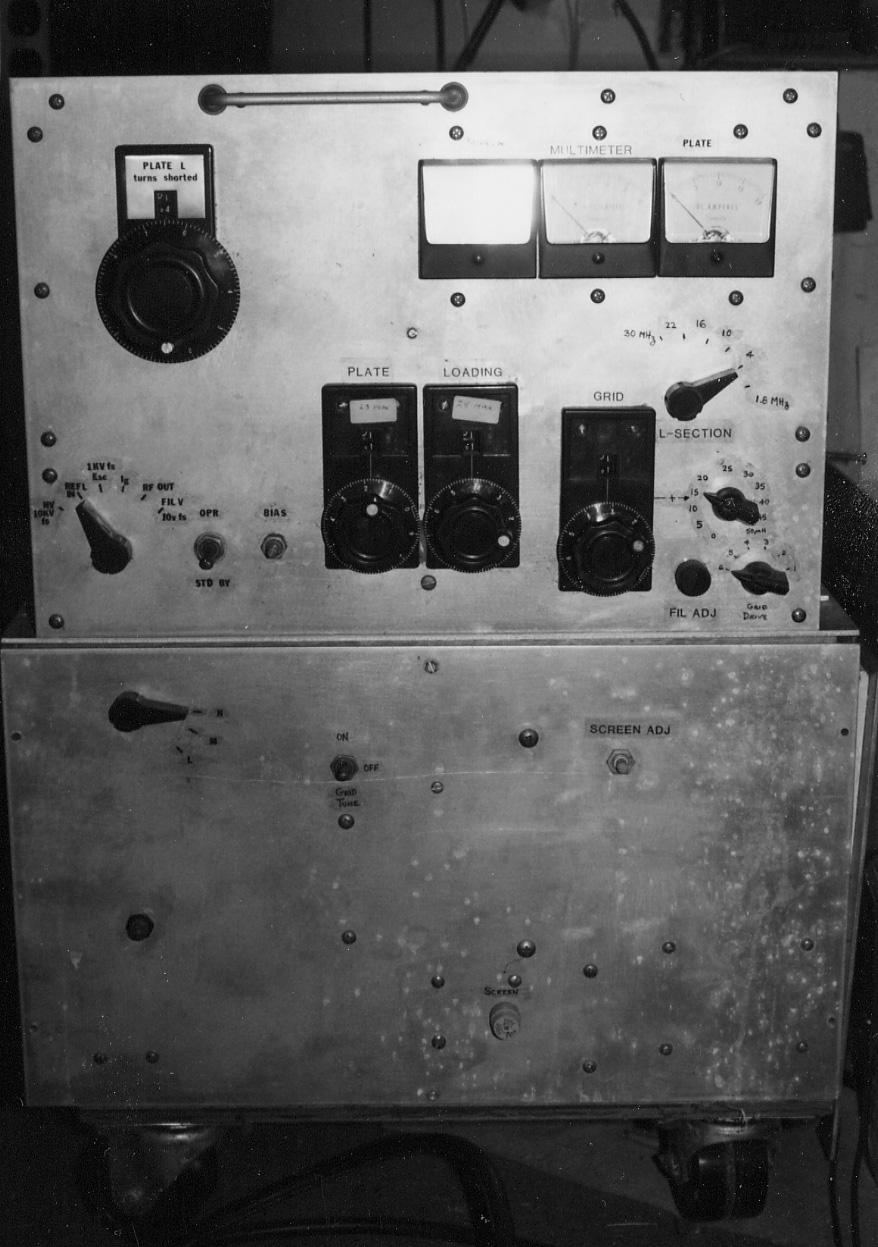
Photographs of amplifier construction using ordinary hand tools.
8169/4CX3000A - Overall view. Top view. Chassis view. View of sound absorbing panels. . A third sound absorbing panel is above the anode cooler, which is not shown in the photograph.
8169: Top: Starting at upper left: 50uH choke from Load-C to gnd. L section of tank. Load-C, 2000pF, 5000v. Two, fixed 750pF vacuum C for Load C padder. // Next row: Low bands HV-RFC. High-bands HV-RFC. Neutralizing bridge, capacitive voltage-divider. DC blocking C. Tune-C, 500pF, 15kV. 22uH variable inductor (tank). // Last row. Tube. 10m tank coil. Spark gap w. series R. . .
Chassis -- Starting at upper left. Y-330B tube socket. RF input relay (RJ1A) and 0mA bias supply. 50-ohm reflectometer for adjusting grid roller coil (small aluminum box with BNC fittings. Coil ends of two RJ-1A output relays (one hidden). Filament transformer. // Next row from left. Bifilar 1:4, 50/200 ohm input matching transformer. Grid DC blocking capacitor and grid terminal. [blue] filter capacitor for bias supply. HV meter multiplier resistor. // Next row: Ferrite core padder inductors to allow grid roller-coil to cover lower frequencies. . Grid roller coil (5.5uH). Load vacuum cap. right angle drive. Tune cap right angle drive. // Next row: Grid termination R. (probably should have been located closer to the grid terminal.) // Last row. Filament rheostat. Plugs for nterconnecting cables. Multimeter switch.
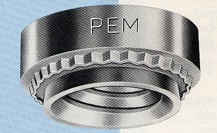
Illustrations of of PEM nuts from Pennsylvania Engineering and Manufacturing Corp. catalog. X-ray view. Optical view. .
END.