REV = 20131010
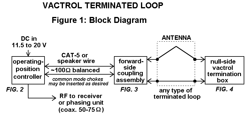
Block Diagram is shown in Figure 1.
Figure 1

Operating-Position Controller is shown in Figure 2.
Figure 2

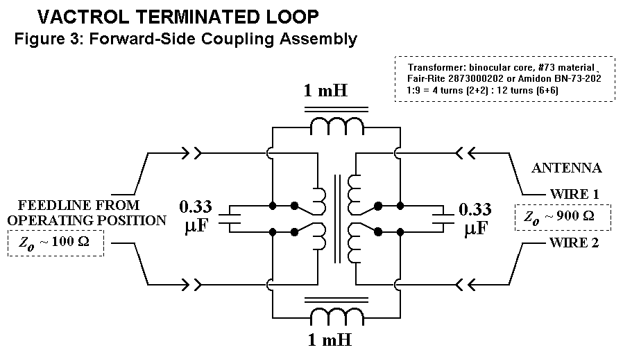
Forward-Side Coupling Assembly is shown in Figure 3.
Figure 3

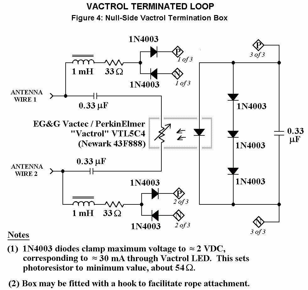
Null-Side Vactrol Termination Box is shown in Figure 4.
Figure 4

Low impedance input amplifier links:
W7IUV amplifier
secondary W7IUV link in case the one above doesn't work
RPA-1 amplifier that can be substituted for W7IUV amp
BBA-C1 amplifier
Medium impedance input amplifier links:
Wellbrook FLG100LN amplifier
BBVA-A amplifier
BBVA-B amplifier (schematic)
BBVA-B amplifier (assembly)
High impedance input amplifier links:
Clifton Laboratories Z10130A amplifier
BUF-B buffer amplifier (pages 16 and 17 of DXP-1 article)
LH0063CK-based buffer amplifier
assorted buffer amplifiers
Other links:
SuperLoop drawing with cardioid pick-up pattern (passive version) (B. Conti)
BACK TO RF CIRCUITS MAIN PAGE


