Motorola index
Home page
on a Motorola 16-channel
GM300 Mobile Radio
Transcribed by Robert W. Meister WA1MIK

|
Maxtrac Index Motorola index Home page |
Using the Channel Select Inputs on a Motorola 16-channel GM300 Mobile Radio Transcribed by Robert W. Meister WA1MIK |
|
All 16 channels on a 16-channel GM300 can be remotely selected through 5 pins on the 16-pin accessory connector. It would seem that if you've modified the software to allow 32 channels, this scheme will also work to select up to 31 of those channels.
There are two parts to using this: software (configuring the radio) and hardware (wiring the circuit and connecting it to the radio).
Software Section:
You must program the accessory connector using the Radio Service Software. Follow these steps:
| Pin # | Description | Data Dir. | Debounce | Act. Level |
|---|---|---|---|---|
| 6 | Channel Select 1 | Input | No | Low |
| 8 | Channel Select 2 | Input | No | Low |
| 9 | Channel Select 3 | Input | No | Low |
| 12 | Channel Select 4 | Input | No | Low |
| 14 | Channel Select 5 | Input | No | Low |
Hardware Section:
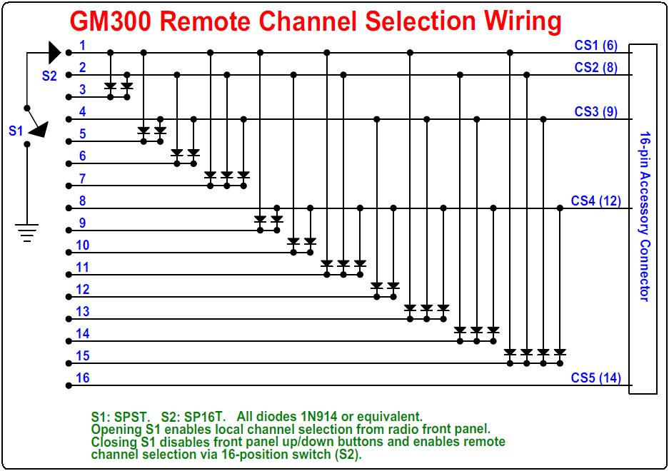
Insert wires into positions 6, 8, 9, 12, and 14 of the accessory connector and wire them as shown on the schematic below.
The diagram depicts all 16 channels remotely selectable over 5 wires, using diodes to activate the desired channel select inputs of the radio. For applications requiring fewer channels, just delete the unneeded portions of the circuit. For example, if only two channels are required, this can be accomplished without any diodes by connecting Channel Select input 2 (pin 8) to ground through an SPST switch. When the switch is closed, channel 2 is selected; when the switch is opened, channel 1 (or whatever channel was previously set from the front panel) is selected. With none of the Channel Select input pins are grounded, channel selection may be accomplished normally using the radio's front panel up/down buttons. When a channel selection has been made remotely, by grounding one or more of the Channel Select input pins, the radio's front panel up/down buttons are inoperative.
If you have configured and programmed your radio to accept 32 channels, this scheme can be expanded by using a bigger rotary switch and adding more diodes to select the additional channels. Just remember to activate the Channel Select 5 pin for channels 16 and above.
You can connect a repeater controller or other digital interface to the same Channel Select input pins. These should be open-collector and active pull-down to a low voltage (under 0.7VDC) to select the channel. The Channel Select inputs operate in a simple binary code according to the table below (L = Low or grounded, H = High or floating). Note that you can't actually select channel 32 remotely, but you can select channel 32 via the front panel up/down buttons, then when all of the Channel Select inputs pins are high, channel 32 will be selected.
| Channel | CS5 | CS4 | CS3 | CS2 | CS1 |
|---|---|---|---|---|---|
| Front Panel | H | H | H | H | H |
| 1 | H | H | H | H | L |
| 2 | H | H | H | L | H |
| 3 | H | H | H | L | L |
| 4 | H | H | L | H | H |
| 5 | H | H | L | H | L |
| 6 | H | H | L | L | H |
| 7 | H | H | L | L | L |
| 8 | H | L | H | H | H |
| 9 | H | L | H | H | L |
| 10 | H | L | H | L | H |
| 11 | H | L | H | L | L |
| 12 | H | L | L | H | H |
| 13 | H | L | L | H | L |
| 14 | H | L | L | L | H |
| 15 | H | L | L | L | L |
| 16 | L | H | H | H | H |
| 17 | L | H | H | H | L |
| 18 | L | H | H | L | H |
| 19 | L | H | H | L | L |
| 20 | L | H | L | H | H |
| 21 | L | H | L | H | L |
| 22 | L | H | L | L | H |
| 23 | L | H | L | L | L |
| 24 | L | L | H | H | H |
| 25 | L | L | H | H | L |
| 26 | L | L | H | L | H |
| 27 | L | L | H | L | L |
| 28 | L | L | L | H | H |
| 29 | L | L | L | H | L |
| 30 | L | L | L | L | H |
| 31 | L | L | L | L | L |
You may have noticed that the data pattern is simple hexadecimal encoding. There are rotary switches that will output this sequence directly. You can then eliminate the diodes and all that wiring and connect the switch directly to the Channel Select input pins to choose your channel. If you select the highest channel from the front panel, you can then access all channels with the rotary switch. Hex switches come in various sizes and number of positions, so if you don't need the full capacity of the radio you can get a smaller switch.
Wiring Diagram:
Click on the image for a larger view.
Contact Information:
The author can be contacted at: his-callsign [ at ] comcast [ dot ] net.
Back to the top of the page
Maxtrac Index
Motorola Index
Back to Home
This article first posted 23-Oct-2015.
This page was last updated on 24-Oct-2015
This web page, this web site, the information presented in and on its pages and in these modifications and conversions is © Copyrighted 1995 and (date of last update) by Kevin Custer W3KKC and multiple originating authors. All Rights Reserved, including that of paper and web publication elsewhere.