20m to 10m link coupled antenna tuner
My antenna is 136 feet loop of 6 sq. mm. plastic insulated wire
( used in household wiring ) strung 30 feet up with four supports.
This is a
HOHPL,
described by antenna Guru L.B.Cebik.
This 40m loop is fed by homebrew ladder line. Ladder line is made with 4 sq. mm.
plastic insulated wire with two inch spacing. This antenna can be used from 40m to 10m
with balanced tuner. This project is about a link coupled antenna tuner using locally
available material for 20m to 10m range, without swapping coils.
Have a separate a 40m link coupled tuner.
Detailed discussion of link coupled antenna tuner By L.B.Cebic is a
5-part article.
Most of the article is way above my head. In Part-5 encountered something familiar,
the component values.
Here is the circuit of the finished tuner.
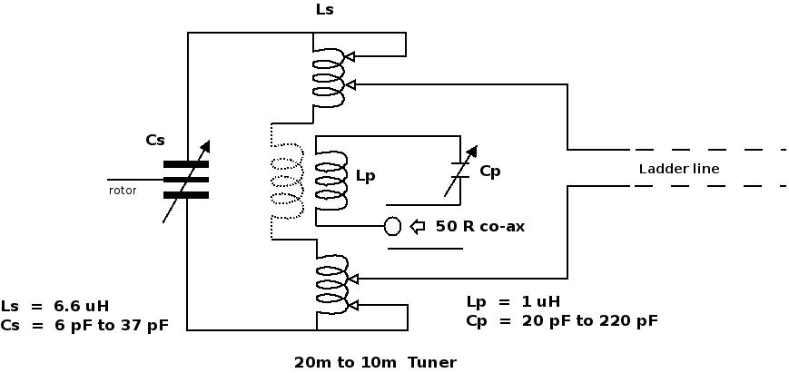
Primary and secondary inductors were made with 6.35 mm. OD.
copper tube with 0.48 mm.wall thickness. Got the tube from
refrigeration accessories shop. Coils were formed over a three inch
OD. plastic pipe. Coil outside diameter was three and half inch,
when it came off the 3 inch plastic pipe. The copper tube appeared
to be made from impure copper. This was felt during coil winding.
Tubes made with electrolytic copper should have been more malleable.
Primary inductor has two and half (2.5) turns. Secondary inductor
has two sections placed on either side of the primary. Each
secondary section has about five and three fourth (5.75) turns.
Two sections of secondary inductor are connected with a
Teflon covered wire passing through the hole of the primary copper
tube.
A 100 pF to 250 pF primary capacitor and a 10 pF to 30 pF
secondary capacitor should be OK for 20m to 10m. Finding suitable
high voltage variable capacitors within my budget proved to be very
difficult. Had some sad experience of building conventional high
voltage variable capacitors for 40m tuner.
High voltage butterfly capacitor can be made with glass epoxy
copper clad laminates.This is shown in F. Dörenberg's (N4SPP)
page.
This idea seemed to be mechanically simpler than conventional variable capacitors. Loss in glass epoxy
dielectric would be more than that of air; this is to be
accepted.
Homebrew high voltage variable capacitors
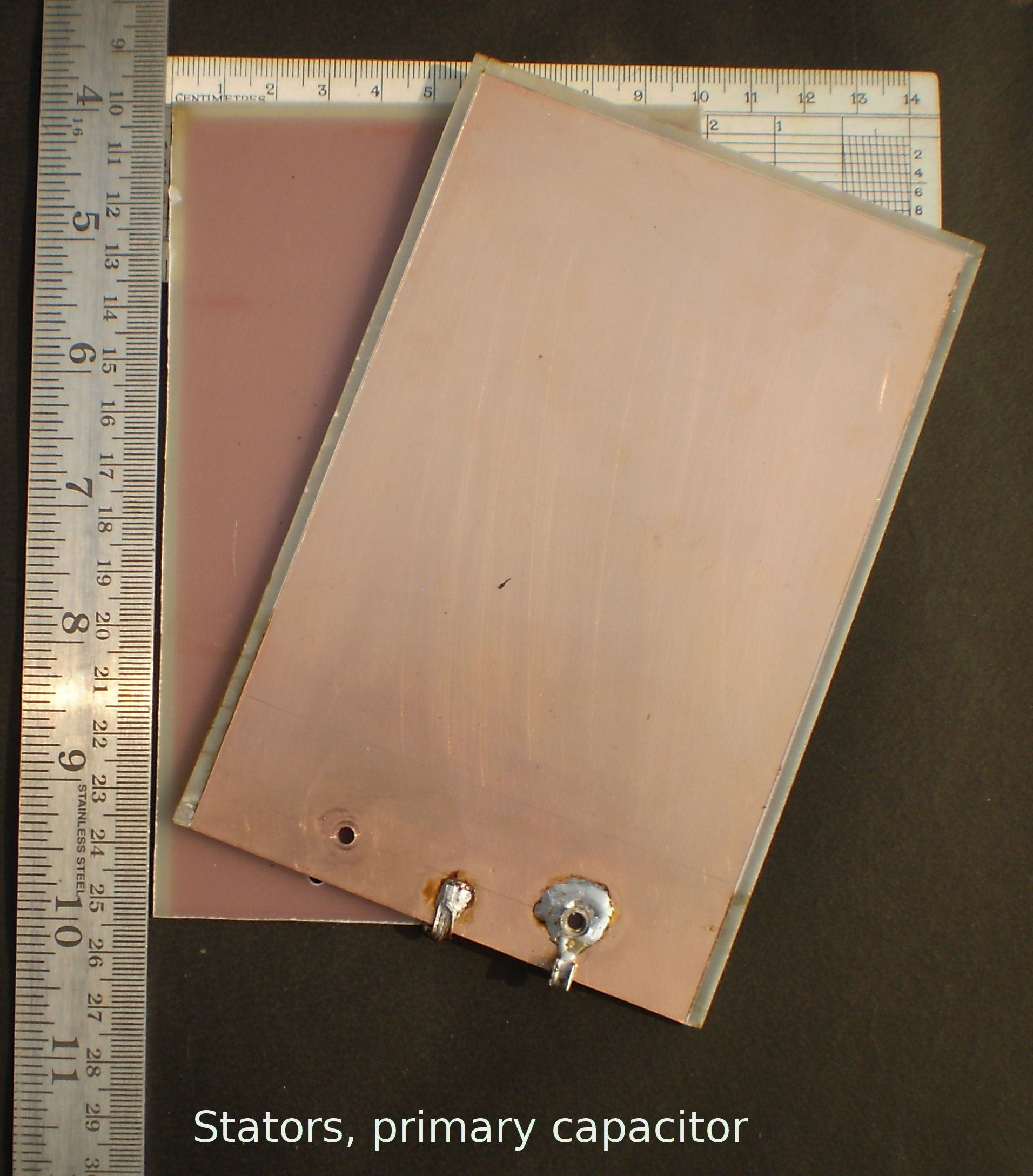
Two stators and one rotor are used for the primary capacitor.
Stators are made from glass epoxy copper clad PCB material. Each
stator is 15.4 cm. x 10.2 cm. x 1.5 mm. All measurements are
approximate. About 3 mm copper was removed on three sides to
prevent arcing. Copper was removed using a knife point and heating
with soldering iron. Etching should have been used. Soldering iron
heat produces tiny ponds of carbon and rosin on the exposed board, degrading
voltage breakdown. Knife cut creates sharp edges, further degrading
breakdown voltage. The corners of copper sides should have been
rounded with etching.
Epoxy sides of two stators face each other and copper sides face
outward. The single rotor is a thin copper sheet that slides
between the epoxy sides. Plastic washers were used between the
epoxy sides to fix the stators on a paper phenolic base board,
Teflon washers were not available. Washers create a narrow gap for
the rotor to slide in and out. A stop prevents the rotor from
disengaging fully from the stators. This dictates minimum
capacitance. Size of rotor is 15.3 cm x 13 cm. and is fixed on an
arm made from unclad glass epoxy board.
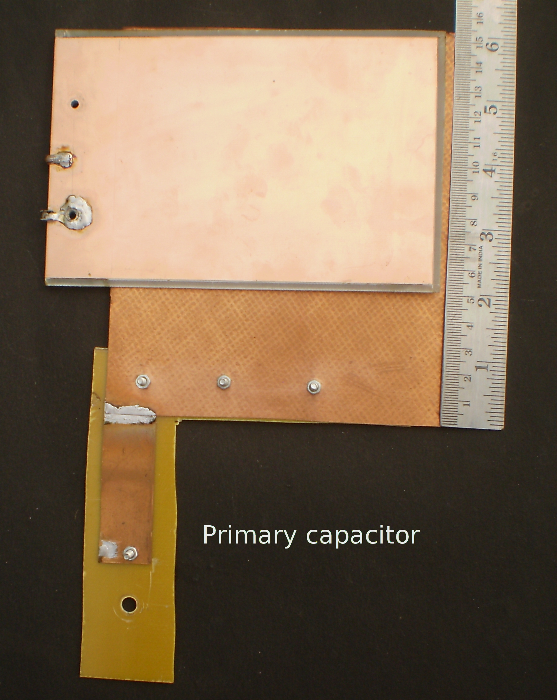
Two stator are connected together at the mounting screws side. Top
upper corner of stators are connected together using a stiff wire
to press the boards closer. This pulls up the maximum capacitance.
This is not shown in above picture. It was done after fixing the
primary capacitor on the tuner.
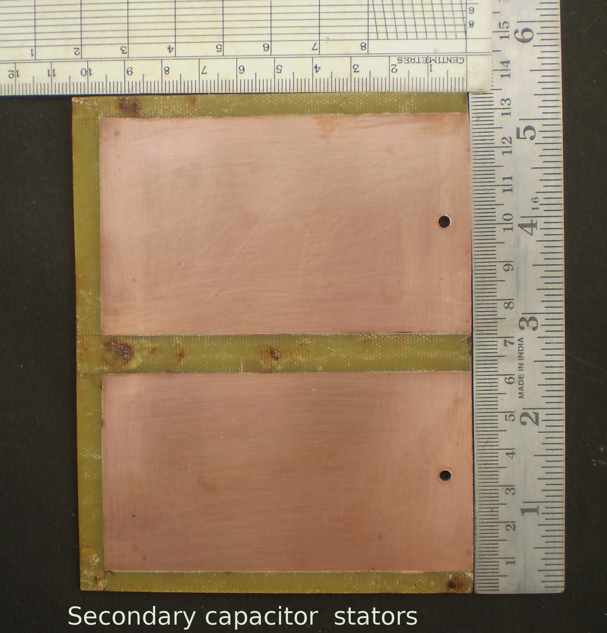
Discolorations caused by soldering iron heat can be seen on
secondary capacitor stators. Size of stator board is approximately
13.6 cm x 10.5 cm x 1.5 mm. One cm. copper was removed in the
middle. About 5 mm. copper was removed from three sides. The rotor
does not come under all the area of stators due to presence of
mounting screws. Stator board is fixed on paper phenolic base board
using thin plastic washers to make room for rotor.
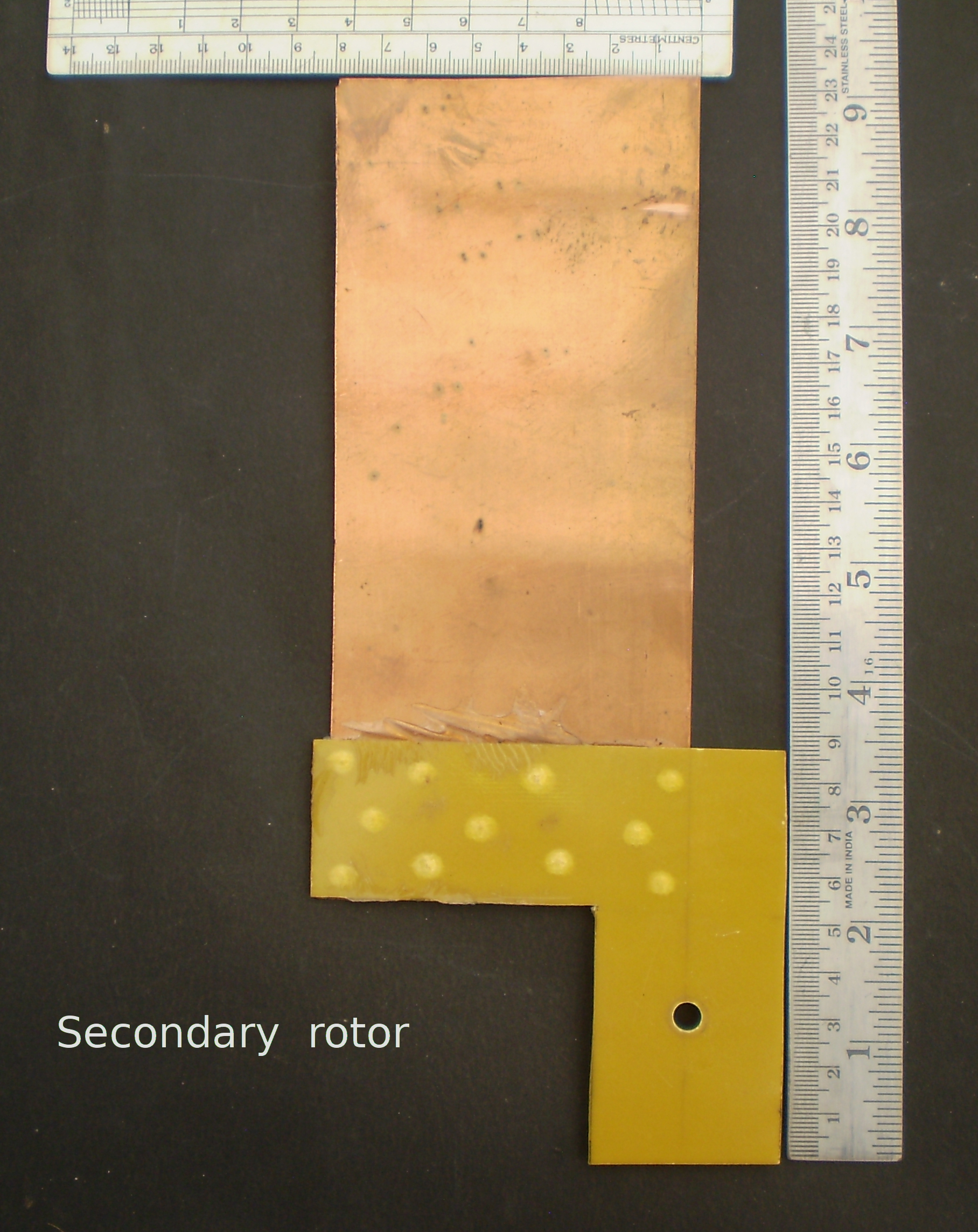
Secondary capacitor rotor is made of thin copper sheet measuring
about 7.8 cm. x 17.8 cm. It is fixed on an arm made of unclad glass
epoxy board using epoxy glue and punching.
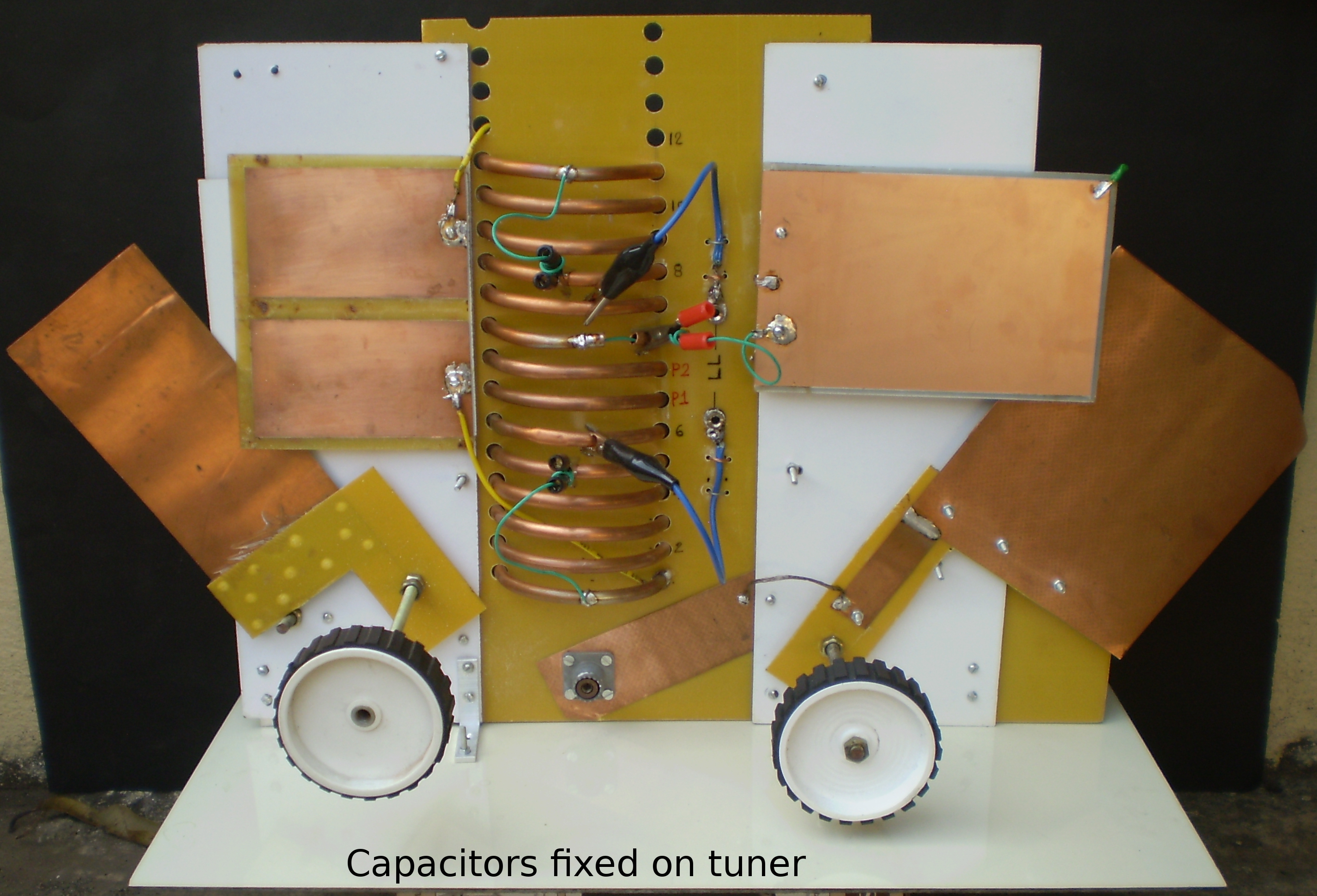
Fixed the inductors and capacitors on base plates to make the
tuner. The picture shows capacitors at minimum value, resting on
their respective stops. Capacitor knobs are robot wheels.
Approximate values of capacitors mounted on tuner but not connected to coils:

Primary    ---  20 pF to 220 pF
Secondary  ---   6 pF to  37 pf
Two arms of the capacitor rotors were cut from a 12 inch x 12
inch glass epoxy sheet. Rest of the sheet was used for fixing
capacitors, inductors and base boards. Two rows of holes, three
inches apart, were made using 7.94 mm. drill bit. Should have used
3.25 inch spacing and a larger drill bit. Screwed in one section of
secondary inductor. Passed a green Teflon insulated wire through
the hole of primary inductor, with about 4 inches sticking out from
each hole. Then the primary inductor was screwed in. Then the
second section of the secondary inductor was screwed in. Two green
wires coming out of primary inductor hole were soldered to the
inner ends of secondary inductors.
For the 40 m to 80 m tuner, the Teflon wire is to be put in the
hole before winding primary. That is another
project.
The green wire coming out of the hole of primary inductor can be
seen in the picture.The other end of the green wire can be seen
from the back side.Ladder line connects to two sockets marked LL,
from the back. Ladder line are connected to the secondary inductor
with clips. These two are blue wires in the picture. Secondary
inductor taps are marked 1 through 12. A short piece of copper tube
can be fixed so that it sticks out of tap 12, however it was not
needed on 20m. The two stators of secondary capacitor are connected
to the two outer ends of secondary inductors. These are yellow
wires in picture. Secondary capacitor stators ( soldered to two
ends of secondary inductor ) are connected to secondary inductor
taps with clips, thus shorting the unused turns. These are green
wires in picture. Primary inductor has three taps P1, P2 and P3.
The SO-239 takes output of rig or inline match indicator.
End to end secondary inductance = 6.6 uH
( about 14 turns including turns passing through hole of primary )

Primary inductance = 1 uH
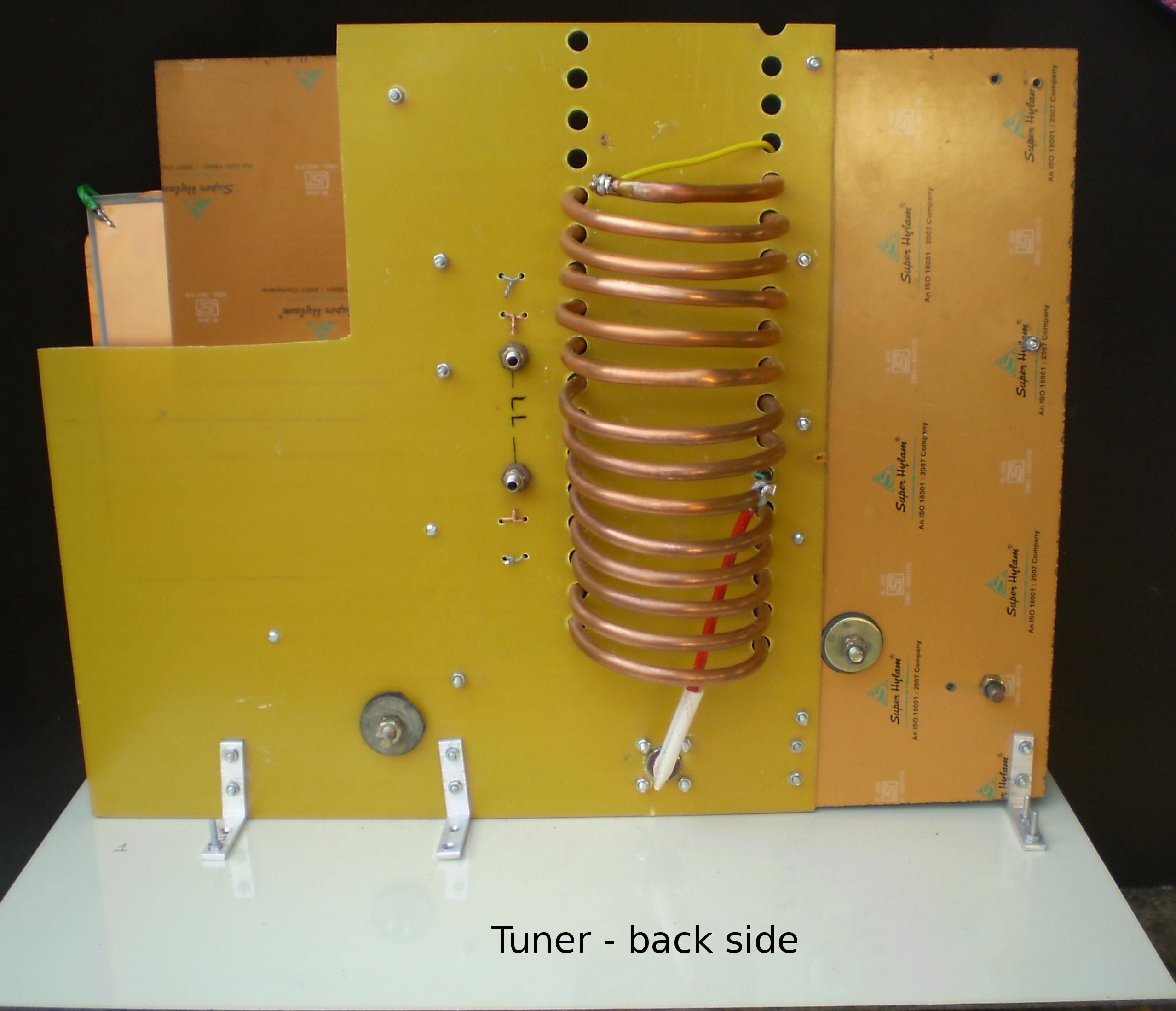
The red wire from SO-239 central pin is connected to start of
primary.
Selection of taps for each band takes time, so rig power was not
used. Output from DDS was used to feed power to a sensitive 50 R
bridge. The bridge circuit is taken from
EMRFD,
but not from chapter-1!
The tuner works on 30m too but it is marginal!

Here are the first set of taps.

Band   Lp     Cs           Ladder line

30m    P3     1 & 11       2 & 10

20m    P3     3 & 10       4 & 9

17m    P3     5 & 7        6 & start of 7

15m    P2     5 & 8        6 & 7

12m    P2     5 & 7        6 & start of 7

10m    P2     5 & 7        6 & start of 7
Going to add more wire to my loop in future. The values in above
table would change.
To get a rough idea of heat produced in the capacitors, JT9 transmission
was used on 28.078 mHz at 50 watts. Immediately afterwards, back of fingers were touched to
copper side of primary and secondary capacitors. Secondary stators
were slightly warm. Detected no change on primary. At 30m similar
slight warming of secondary stators was observed. Both the tests
were carried out with antenna matched.
50 watts is unlikely to fry the capacitors.
While tuning secondary capacitor, felt the need for fine tuning.
Some kind of fine tuning is to be added in future.
A relative power output indicator has to be added in future.
73 ! vu2nil