WHAT IS PHASE
REVERSAL PHENOMENON SIGNIFICANT IN LINE-OF-SIGHT COMMUNICATION?
WHAT IS TEMPERATURE
INVERSION PHENOMENON?
WHAT IS AN
ARTIFICIAL COMMUNICATION SATELLITE?
WHAT IS GEO-SYNCHRONOUS
EARTH ORBIT?
WHAT
IS LATENCY?
WHAT IS A LOW EARTH ORBIT?
WHAT IS IONOSPHERIC
PROPAGATION?
WHAT IS SHORT WAVE
BAND?
WHAT IS MEDIUM WAVE
BAND?
WHAT IS THE SPECIALITY OF
10 MHz BAND?
WHAT
IS SKIP ZONE?
WHAT IS FADE OUT & FADING
Long distance propagation of radio waves depends on an invisible layer of charged
particles, which envelops the Earth. This layer of charged particles known as the
ionosphere has been in existence for millions of years. For those, who pioneered the long
distance radio communication during the early part of the twentieth century, the
ionosphere came as a boon. During the formative days of radio communication, radio
scientists could not come to a definite conclusion about how radio waves propagated round
the world. Both Radio and Television utilise radio wave, a form of electromagnetic wave,
that travels at a velocity of 3,00000 km per second in vacuum. Its
velocity gets changed very negligibly in a different medium, which is insignificant,
because the earth is a very small place with a radius of only 6000-km. Communication
between any two points on the earth is thus almost instantaneous. But electromagnetic
waves travel in straight lines until they are deflected by something. The father of radio,
Gug1ielmo Marconi himself was at a loss to explain how, on 12th December, 1901, he
established the first real long distance wireless communication between St. Johns, New
Foundland, USA and Poldhu in the Southern Tip of England, a distance of more than 3,000
kms across the Atlantic ocean. At that time, it was known that except for very short
distances, the radio waves did not follow the natural curvature of the earth. Earth's
curvature is a direct block to line-of-sight communication. When enough distance separates
the two radio stations so that their antennas fall behind the curvature, the Earth itself
blocks the transmitted signals from the receiver.
TOP
VHF
The radio frequencies above 30 MHz has the tendency to penetrate the ionosphere
making them unsuitable for long distance propagation. So, the range of frequencies from 30
to 300 MHz (also 300 MHz and above), which are placed under the Very High Frequency (VHF)
category are mainly used for line-of-sight communication. The most common example of
line-of-sight communication is the TV Telecast. A TV transmission tower is made as tall as
possible so that its signals can have a wide area of coverage. To receive a TV telecast,
we have to turn our TV antenna (known as a Yagi antenna) towards the TV transmission
tower. In areas where the TV transmission tower is located at a far away place from a
viewer, the viewer has to increase the height of his TV receiving antenna. This means that
both the transmitting and receiving antenna should literally see each other to make the
communication effective. Otherwise there should be some means to redirect the signal back
to the receiver. Artificial Satellites in space (which houses active electronic relaying
device), terrestrial relay station and passive reflectors (the metallic plates we see
above the hills) are employed to extend the VHF coverage. Line-of-sight communication is
considered reliable within a short distance.
TOP
PASSIVE REFLECTORS
To receive radio signals in the VHF ranges at a far away place from their place of
origin, we need some kind of a reflector in between. You might have noticed big metallic
plates on the mountain tops (or on top of other tall structures, which have a similarity
to the roadside signboards. These are passive reflectors, which reflect
VHF and UHF signals to far away places. A passive reflector is an object, which is
not equipped with any kind of electronic circuitry to relay the radio signal.
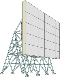
A Passive Reflector to reflect VHF/UHF radio signals
TOP
A NATURAL PASSIVE REFLECTOR
The moon, which had been in orbit for some 5 million years or
more, was used as a natural passive reflector by the U.S. Army Signal
Corps for the first time on 11 January, 1946 by bouncing radar (Radio Detection And
Ranging} signals off the moon during Project Diana. On 29 November, 1959,
voice transmissions were relayed from Holmdel, New Jersey to Goldstone via this same
natural satellite.
The Moon was also used as a reflector of radio waves by the U.S. Army in the 1950s, when
the existing channels between the US mainland and Hawaii failed because of atmospheric
disturbances. This type of radio communication is known as Moonbounce radio
communication. Ham radio operators refer to it as E.M.E., i.e. Earth-Moon-Earth
and this describes exactly what happens; the radio signal leaves the earth, is reflected
back off the moon, and comes back to earth. The reflected signal spreads out, and can be
received at any place on earth where the moon is above the horizon.
What is the phase reversal
phenomenon significant in line-of-sight reception? PHENO TOP
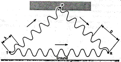
Image source: Practical Wireless Magazine (Issue
unknown)
In case of line of sight reception, there are two components of the signal. One is the
direct signal and other is the signal reflected from the ionosphere. Both the signals
leave the antenna with the same signal phase, but travel different paths to the receiving
antenna. These paths may be of different length. Because the reflected signal suffers 180
degree phase reversal at the point of reflection, the two signals may aid or oppose each
other in the receiving antenna. The resultant signal may be stronger or weaker than the
direct path signal alone which is not desirable.
TEMPERATURE INVERSION PHENOMENON
TOP
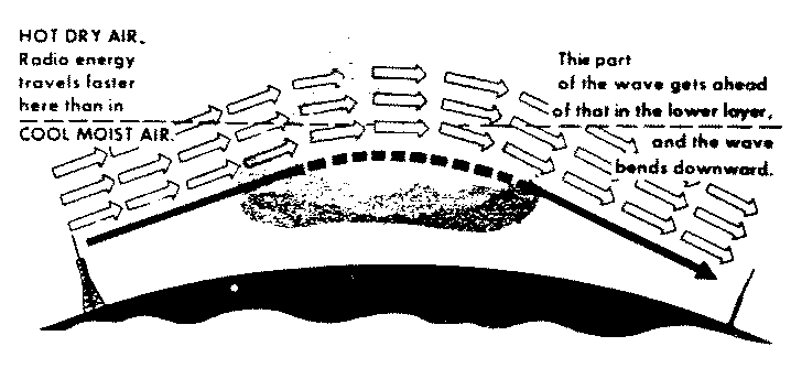
Image Source:
Basic Radio (Vol-6 P:6-127 1969 edition) by Marvin Tepper
The line-of-sight propagation is limited to the optical horizon and it is only about 75
miles for frequencies above 30 MHz; but it is found that in the spring or fall, or
sometimes in summer, this line-of-sight propagation extends to about 500 miles. This is
due to the presence of layer of hot, dry air above a layer of cool, moist air. The direct
waves are bent back which otherwise pass over the receiving antenna.
TOP
ARTIFICIAL COMMUNICATION SATELLITE
In case of using passive reflector to reflect VHF and UHF radio signals, large
signal loss takes place between the transmitter and the reflector and an equal
loss between the reflector and receiving station. It requires significant amount of power
to assure a strong enough signal back on earth after the reflection process has taken
effect. So, radio communication via artificial communication satellites, equipped
with active electronic circuitry, which can re-transmit the received signal with an
amplified power, was another proposition put forward by Arthur C Clarke during the 1945s.
The artificial communication satellites overcome the problems involved in radio signal to
span oceans and continents with sub-marine cables, landlines and terrestrial relay
stations, for long-distance transmission of radio, telephone and television signals. VHF
or UHF(also called microwave) travel in line-of-sight. So, the relay stations to receive,
amplify and retransmit signals must be spaced approximately 35 miles or so because of the
curvature of the earth. The cost of providing enough relay stations to encircle the world
completely would still be prohibitive.
TOP
GEO-SYNCHRONOUS EARTH ORBIT
The visionary idea put forward (1945) by
famous science fiction writer Arthur C. Clarke, that three artificial satellites spaced at
120 degrees intervals about the equator at a distance of 35,200 km above the earth
in a Geo-synchronous Earth Orbit (GEO) would effectively cover the entire globe, soon
became a reality. This orbit is called the "Clarke orbit". A GEO
satellite revolves round the Earth at the same speed as the Earth rotates around its axis
and thus the satellite's position remains static relative to an area on the Earth.
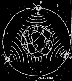
"Clarke Orbit"
Image source:
Entertaining Electronics by E. Sedov |
|
TOP
LATENCY
India's INSAT series of satellites are GEO satellites. Because of their high
altitude, they require high transmission power for communication as a
result of which the land based GEO transmission units are heavy and consequently
unsuitable for mobile users. Another drawback resulting from the high altitude is
called latency. As the distance between the satellite and the land-based
transmitter-receiver is large, radio signals take time to travel from Earth to satellite
and back, resulting in a time lag of 0.24 seconds, a time lag unacceptable in interactive
communication. That is why GEO satellites are used in non-interactive radio
communication such as the Television.
TOP
LOW EARTH ORBIT
Nowadays, a constellation of 66 orbiting communication satellites (known as IRIDIUM)
exists just 780 km above the surface of the Earth classified as Low
Earth Orbiting (LEO) satellites. Because of their lower altitude, latency (time
lag) is almost negligible and user-devices do not have to be very powerful or bulky.
Cellular & mobile phones also utilise frequencies in the UHF range and a city with
cellular facility is divided into some small cells-each cell having its own relay station.
TOP
IONOSPHERIC PROPAGATION
The First proclaimed Radio Amateur (HAM), Guglielmo Marconi was not using VHF or
UHF for his famous Trans-Atlantic radio communication experiment nor was he employing any
artificial relay mechanism. Yet his radio signal traveled half the world. Marconi's
wireless transmitter powered by 2,000 volts from a generator driven by a 32 horsepower
petrol engine pumped out 25,000 watts (25 KW) of power at a carrier frequency of about 328
kHz (Kilo Hertz). Alternately. the wavelength of the radio frequency used was
approximately 915 metres. The formula to calculate wavelength of an electromagnetic wave
is Wavelength in metres = 300/frequency In Mega Hertz. The dial of a radio receiver also
marks either wavelength or frequencies or both.
On frequencies below 30 MHz, long distance radio communication is the result of
refraction (bending) of the wave in the ionosphere. Oliver Heaviside
in England and A.E. Kennally in America,in 1902, suggested that there
must be some kind of reflecting medium in the upper atmosphere that caused the radio waves
to be returned to Earth at considerable distances from the transmitter. Under the action
of solar radiation and the hail of meteorites, an ionised layer is formed in the upper
part of the Earth's atmosphere. In this layer, the neutral air molecules are decomposed
into ions and electrons and the whole layer presents a chaos of charged particles.
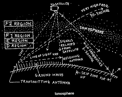
Short wave or High Frequencies (HF) in the range of 3-30 MHz propagates
through this invisible layer which consists of charged particles located at altitudes of
between 250 and 400 km in the atmosphere surrounding the Earth. This layer of
charged air particles called F2 layer of the ionosphere plays
a vital role in HF propagation by reflecting or refracting the HF signals back to Earth.
The ionosphere has got different sub-layers. The lowest is D-layer at
altitudes ranging from 50 to 90 km. High frequencies (3-30 MHz) penetrate
this layer, while low frequency (LF: 30-300 kHz) or medium waves are absorbed by this
layer. To some extent LF and Very Low Frequency (VLF: 3 to 30 kHz) are reflected during
daytime. It slightly scatter and absorbs HF. This layer subsists only during daytime.
The E-layer extends from an altitude of 100 km. Though
sunlight is an important factor for its existence, after sunset also it exists for some
time. This layer is responsible for evening and early night time propagation of medium
waves (low frequency) upto a distance of about 250 km. Propagation of
lower short wave frequencies, e.g. 2 MHz , up to distance of 2000 km at daylight
time is due to this layer. It has little effect at night.
F1 layer exists at an altitude of 200 km
during daytime and its characteristics are very similar to E-layer which emerges into F2
layer at night. F2 layer is the most important layer which exists at
altitudes ranging from 250 to 400 km and HF long distance propagation round the clock is
due to this layer. The behaviour of this layer is influenced by the time
of the day, by season and by sunspot activity. F2
layer was formerly known as Appleton layer. This layer has a high
ionization gradient. This layer exists both in the daytime and nighttime. Since at such an
altitude air density is extremely low, the free ions and electrons (due to the action of
ultraviolet radiation from the Sun) can not recombine readily and so can store energy
received from the Sun for many hours; that is the reason the refractive property of this
layer changes only to a negligible extent during day and night. The path which the short
wave signal follows through the F2 layer is in reality a curved one. Degree of
the curve depends on the angle of incidence of the wave, ionization gradient of the layer
and frequency of the signal.
TOP
SHORT WAVE BAND
Short wave radio signals (radio signals which fall in the range of 3
to 30 MHz) are reflected from the ionosphere just as light rays are
reflected from the surface of a mirror, or sound wave from a barrier. likewise, this layer
can be compared to the edge of a billiard table. Communication specialists use this layer
like the edge of a billiard table: if the ball does not go straight into the pocket, it
can be directed on the rebound. In the same way, the short wave signals radiated by
distant radio stations get to our receiver on the rebound. They can continue traveling to
several places round the world, for the Earth is also like the edge of a billiard-table.
TOP
MEDIUM WAVE BAND
Unlike the short wave or high frequencies (HF), the frequencies ranging from 300
kHz to 3000 kHz, are known as medium frequencies and the band is known as Medium Wave band.
There is very little daytime reflection of medium wave radio signal from the ionosphere
resulting in a coverage of about 100 kms only.The ionosphere is located above the
troposphere, starting at an altitude of 30 miles above the surface of the earth and
extending upto an altitude of 260 miles. The troposphere is the region of the earth's
atmosphere immediately adjacent to the earth's surface and extending upward for some tens
of kilometres. Radio waves are refracted or bent slightly, when traveling from one medium
to another. Refraction is caused by a change in the velocity of a wave when it crosses the
boundary between one propagating medium and another. If this transition is made at an
angle, one portion of the wave-front slows down or speeds up before the other, thus
bending the wave slightly. Radio waves are commonly refracted when they travel
through different layers of the atmosphere, whether it is highly charged ionospheric
layers 100 km and higher, or weather-sensitive area near the Earth surface. When
the ratio of the refractive indices of two media is great enough, radio waves can be
reflected, just like light waves striking a mirror.
The role of ionosphere in radio wave propagation can be discussed only in terms of
the different radio frequencies available for communication and in the light of the
existence of different ionospheric layers. Although the various methods used confirmed the
theories of Heaviside and Kennally, there were differences between the results obtained by
Professor Appleton and other investigators. It was discovered that there was not one, but
two reflecting layers. The first trials with pulse waves in 1925 by Breit and Tuve
in America were successful in that the method proved to be much more practicable.
Since radio waves take 1 millisecond to travel 300 km, the height of the
layer established from the first echo in this case was found to be 300 km. The ionised
layers were designated with letters of the alphabet by E. V. Appleton,
the lowest layer known at a height of about 60 to 90 km being called the D
region because this is not strictly a layer but a relatively dense part
of the atmosphere where atoms are broken up into ions by sunlight that recombine very
quickly. The amount of ionisation therefore depends on the amount of sunlight and
the region has the effect of absorbing the energy from a radio wave, particularly at
frequencies in the band of 3 to 4 MHz and frequently as high as 7 MHz.
Most of the long distance communication results from ionisation of the F
layer, the most applicable radio bands in the High Frequency being 3.5
MHz, 7 MHz, 14 MHz and 21 MHz.
The layer height may vary from a little over 200 km to as high as 400 to 500 km
depending on the time of the year, latitude and time of
the day and particularly the amount of sun-spot activity. During
the peak period of the 11 year maximum sun spot activity cycle,
propagation via the F layer extends up to around 30 MHz.
The problem of variable propagation conditions can be partially overcome by using
frequency diversity, in which an allotted wireless communication network is provided with
several frequency assignments spanning the high frequency (short wave) band of
frequencies. The radio operator can thus choose the channel that gives the best results at
any given time.
The 1800 kHz (1.8 MHz or 160 metre band) band suffers from extreme daytime D-layer
absorption. Even at high radiation angles, virtually no signal can pass
through the F layer and daytime communication is limited to ground-wave coverage.
At night, the D layer quickly disappears and world- wide 160m
communication becomes possible via F2-layer skip. Atmospheric and
man-made noise limit propagation of this band. Tropical and mid-latitude thunderstorms
cause high levels of static in summer, making winter evenings the best time to work long
distance at 1.8 MHz. A proper choice of receiving antenna can often significantly reduce
the amount of received noise while enhancing desired signals.
The 3500 kHz (3.5 MHz or 80 metre band) is the lowest HF band,
which is similar to 160 m in many respects. Daytime absorption is significant, but not
quite as extreme as at 1.8 MHz. High-angle signals may penetrate to the E and F layers. Daytime
communication range is typically limited to 400 km, primarily via ground-wave
propagation. At night, signals are often propagated halfway around the world. As at 1.8
MHz, atmospheric noise is a nuisance, making winter the most attractive season for
the 80 m. The 7000 kHz (7 MHz or 40 metre) band is useful for daytime
communication up to a distance of 800 km via E and F layers. Long distance
world-wide communication takes place in this band through F2 layer.
TOP
10 MHz BAND
The 10 MHz or 30 metre band is unique because it shares characteristics of
both daytime and night-time bands. Communication up to 3000 km is typical during
daytime, and this extends halfway around the world. The band is generally open via
F2 on a 24-hour basis. The International Telecommunication Union (ITU) has
allotted 10,100 kHz to 10,150 kHz to the radio amateurs in Region 3 countries. This small
slot was made available to amateurs in WARC-79 (World Administrative Radio Conference,
1979) While most of the countries have released it for use by the ham radio operators,
Indian hams are still getting deprived in respect of allocation of this small slot. There
should not be any problem in releasing the slot to the Indian ham radio operators, as it
would be on secondary shared basis.
Despite the fact that the introduction of artificial communication satellites for
long distance radio communication made communication more reliable and there is very
little role left to be played by the ionosphere in the professional telecommunication
networks, it still draws the attention of communication enthusiasts, arm forces, spies and
ham radio operators. Ionosphere is a gift of nature. Unlike the costly artificial
satellites, we need not subscribe to anybody to get access to a facility, which can
transfer our radio messages to distant parts of the world. It is worthwhile for a radio
user to learn more about the ionosphere.
TOP
What is "Skip Zone"?
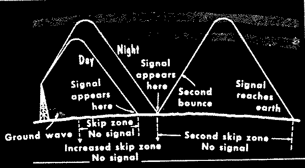
Under the action of solar radiation and the hail of
meteorites, an ionized layer is formed in the upper part of the Earth's atmosphere. In
this layer, the neutral air molecules are decomposed into ions and electrons and the whole
layer presents a chaos of charged particles.Short wave radio signals are reflected from
this layer just as light rays are reflected from the surface of a mirror, or sound from a
barrier.Likewise, this layer can be compared with the edge of billiard table: if the ball
does not go straight into the pocket, it can be sent on rebound. In a situation, a radio
receiver set located at a distance of 200 kilometres (say) away from the wireless
transmitting station can not receive signals from the transmitting station. This is
because the ground waves are stopped by the Earth's curvature and the sky wave will not
reach the receiver, because it bounces again more than 200 kilometres way. So some
'blind zones' are formed and if the receiver is located in that blind zone it will receive
no signal or very weak signal. In such a situation, another station can relay the
message to the target station. The distance of the intended receiver from the
transmitter is then termed as 'skip distance'. So it is not always necessary that
a receiving station located nearer (than a station located further away from the
transmitting station) to the transmitting station will be able to receive its
signal.
FADE OUT & FADING FADETOP
Fade-out
It is the gradual phenomenon, that take place with the change of time of the day. Fadeout
of radio signal is related to the ionization gradient of the ionosphere, which decreases
in absence of sunlight. Since ionization is intense during day light hours, higher
frequency (like 14 MHz and 21 MHz) of the short wave spectrum can be used during daylight
hours. As the night approaches, signal strength at that higher frequency decreases. Using
a frequency at the lower edge of the HF spectrum (e.g. 7 MHz) will yield satisfactory
result against this fadeout.
Fading
As distinct from fade-out, fading is the constant variation of the received strength of
radio wave. To the listener it appears as gradual rising and falling of the volume. The
signal waxes and wanes and at times even drops below usable values. This phenomenon is
manifested chiefly in long-distance transmission. It is caused by multiple reflections
from the ionsphere which cause two or more waves from the same transmitter travel over
different paths of different lengths and hence differ in phase and amplitude when they
arrive at the receiving aerial.
(Page maintained by Sandeep Baruah,
Ex-VU2MSY)