| |
When Dr. Ashutosh, VU21F suggested
publication of information on my vintage valve type
amplifier for NR60, I was hesitant. I
guess lot many hams, now-a-days, are not at all aware
ofsomething called vacuum tubes &hence there would be
no takers
for such a recipe. However my choice of such an amplifier
aheadof NR60 was based on the following considerations:
1. Cost factor
2. Ruggedness-cannot be immediately damaged
because ofmismatch
3. Good possibility of taming for multi-band
operation without elaborate &dedicated
filters for different bands
4. Low TVI
5. Simplicity of construction, switching etc.
If you are convinced that those are good enough reasons
for a little tactical move backward, may perhaps switch
on the soldering iron.
However, before you start please make certain that the
basic NR60 board is working absolutely OK without any
problem. It
must be tested on-the-air with local hams for quality
& acceptability. Both the NR60 board & VFO must
be shielded. If you use any
premixing technique, the associated circuitry also should
be adequately shielded. The power supply should be made
in two
separate well-shielded cabinets- one for the low voltage
(12V& 25 Vdc &the other for the HV supply for the
valves. Last but not
the least, the valves &associated circuitry must also
be shielded appropriately with no possible interaction
between the grid &
output circuits.
Prospective constructors should refer
to Radio Handbooks & other standard literature for
more information & confidence. The circuit is
straight forward &generated from available literature.
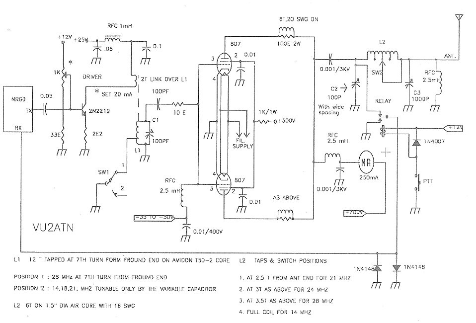
Here is the circuit diagram with values marked: The
transistorized linear driver is expected to swing up to
60 to 70 mA with signal (AF) input. The transistor has to
be biased at 20 mA &must be heat-sinked properly. The
25V collector supply need not be switched while going to
AM mode. However the 12 V supply must be switched.
Similarly for the valve stage, only screen supply shall
be disconnected during receive mode. It is needless to
say that antenna must be switched between Tx & Rx as
shown in the circuit diagram.
While dealing with vacuum tubes, please
remember all safety aspects &go through very
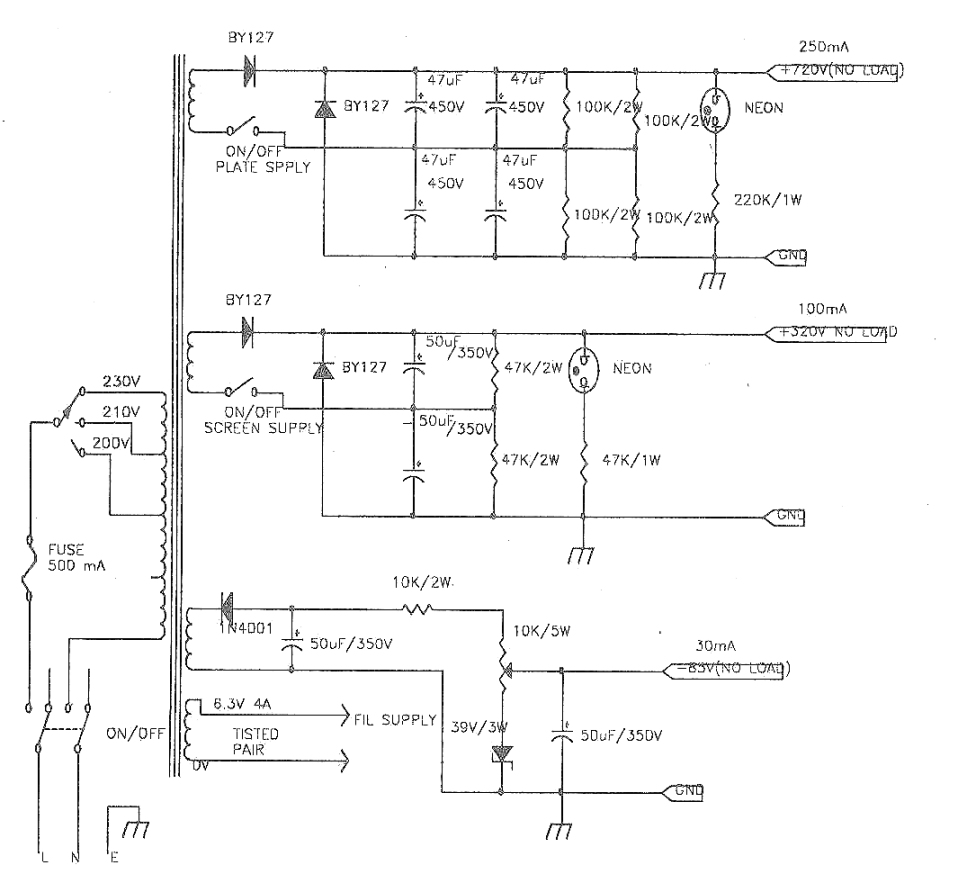
carefully the standard literature. The Power Supply: The
power supply for the PA stage is straight forward &as
shown in the diagram. The power supply uses a single
transformer for I supplying the filament supply, plate
&screen voltages &also the I bias supply. The
transformer shall not be available off the shelf and it
has be to ordered with somebody. However, arrangements
can be made for supplying the requisite voltages &
current from an alternative source. My set-up is based on
a circuit for such a
transformer, made available to me by my good old friend
Debu, VUPB and the transformer was designed
&constructed by grand OM of Amateur Radio Ganeshda,
VU2LL(now silent key). Most probably, such a power supply
is used in HW 101, manufactured by Heathkit.
The components are mounted on an aluminum chassis over
tag strips &no PCBs have been used. All the switches
are mounted on front panel including the bias-control
& neon indicators. The transformer has been mounted
on the top surface of the chassis &all other
components &wiring on the bottom side. Slightly
oversize components have been used for reliability. For
safety reasons, the chassis must be earthed properly
&any prospective constructor is requested to please
go through the chapter on Power Supplies in any standard
Radio Handbook &other literature.
The above configuration (the AF amplifier and the power
supply) Has been working satisfactorily for more than 3
years.
I hope there will be some takers, HI.
Happy construction!.
VU2ATN
Atanu Das Gupta
|
|